Configuration procedure – H3C Technologies H3C SR8800 User Manual
Page 84
75
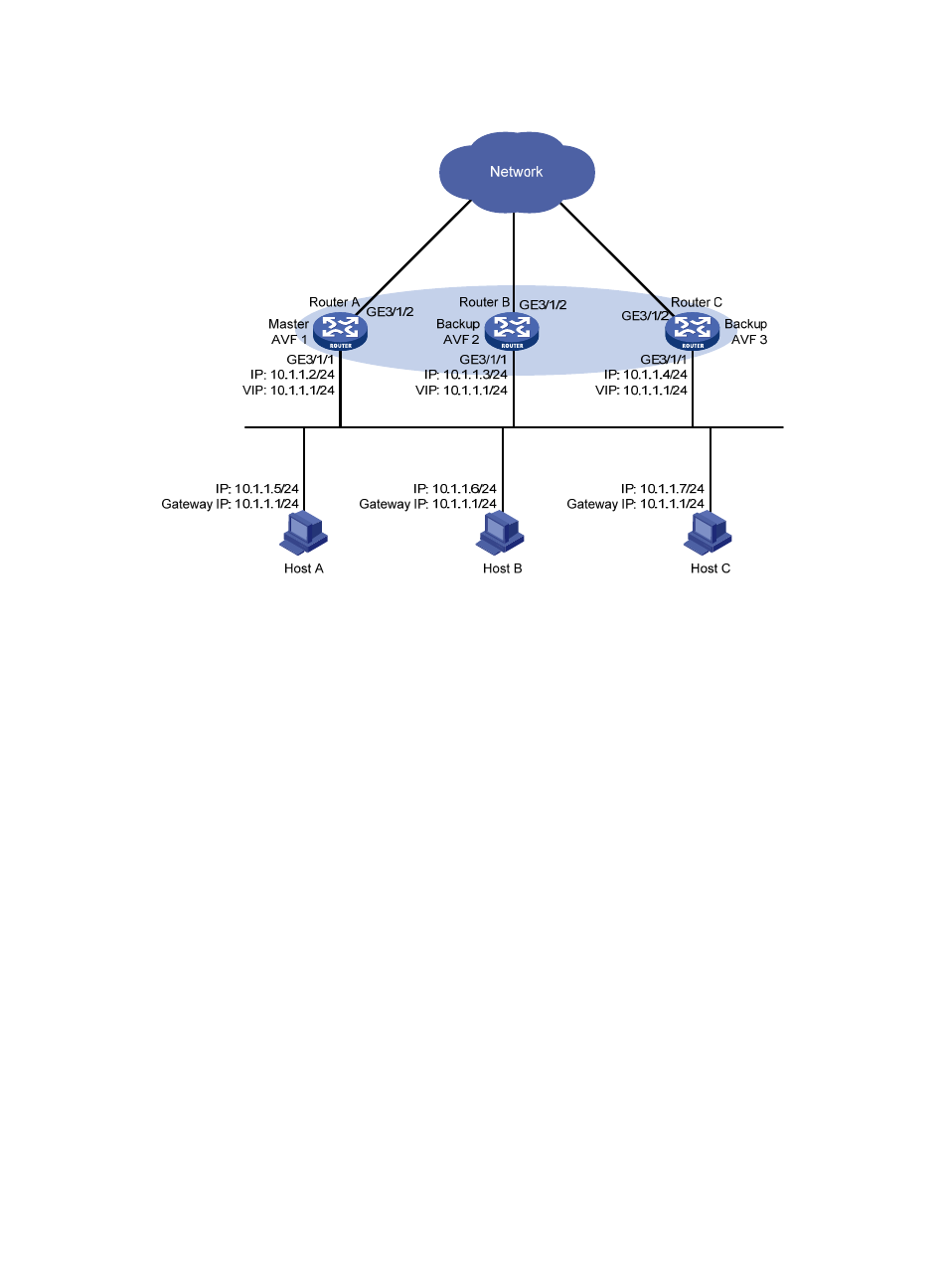
Figure 24 Network diagram
Configuration procedure
1.
Configure Router A:
# Configure VRRP to work in load balancing mode.
[RouterA] vrrp mode load-balance
# Create VRRP group 1 and configure its virtual IP address as 10.1.1.1.
[RouterA] interface GigabitEthernet 3/1/1
[RouterA-GigabitEthernet3/1/1] ip address 10.1.1.2 24
[RouterA-GigabitEthernet3/1/1] vrrp vrid 1 virtual-ip 10.1.1.1
# Set the priority of Router A in VRRP group 1 to 120, which is higher than that of Router B (110)
and that of Router C (100), so that Router A can become the master.
[RouterA-GigabitEthernet3/1/1] vrrp vrid 1 priority 120
# Configure Router A to work in preemptive mode so that it can become the master whenever it
works normally. Configure the preemption delay as five seconds to avoid frequent status
switchover.
[RouterA-GigabitEthernet3/1/1] vrrp vrid 1 preempt-mode timer delay 5
[RouterA-GigabitEthernet3/1/1] quit
# Create track entry 1 to associate with the physical status of GigabitEthernet 3/1/2 on Router A.
When the track entry becomes negative, it means that the interface fails.
[RouterA] track 1 interface GigabitEthernet 3/1/2
# Configure the VFs to monitor track entry 1, making the weight of Router A decrease by more than
245 (250 in this example) when track entry 1 turns to negative. In such a case, another router with
a higher weight can take over.
[RouterA] interface GigabitEthernet 3/1/1