Network requirements, Configuration procedure – H3C Technologies H3C SR8800 User Manual
Page 138
129
Static routing-track-NQA collaboration configuration example
Network requirements
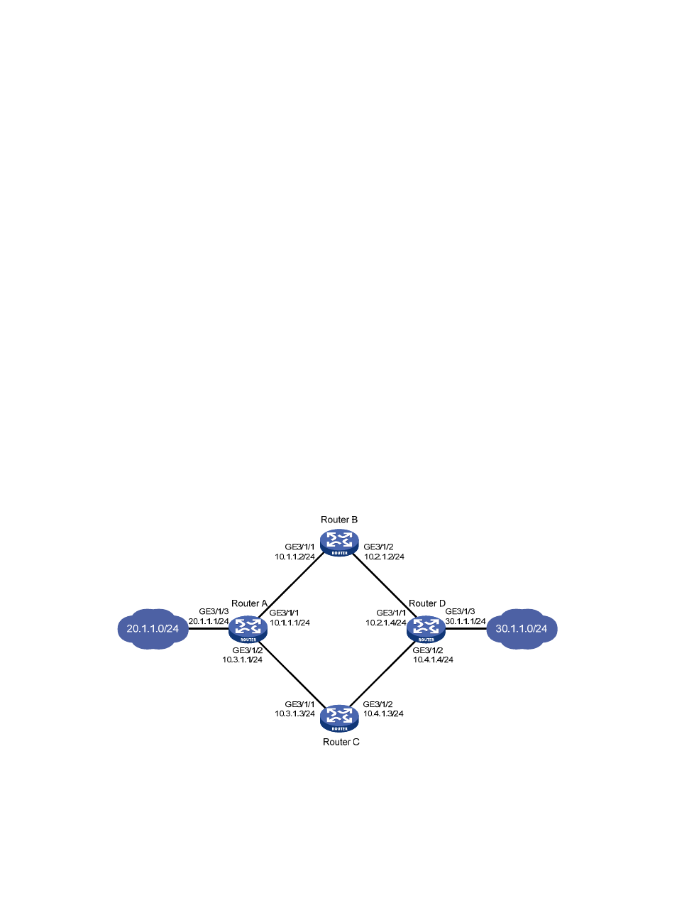
As shown in
, Router A, Router B, Router C, and Router D are connected to two segments
20.1.1.0/24 and 30.1.1.0/24. Configure static routes on these routers so that the two segments can
communicate with each other, and configure route backup to improve reliability of the network.
Router A is the default gateway of the hosts in segment 20.1.1.0/24. Two static routes to 30.1.1.0/24 exist
on Router A, with the next hop being Router B and Router C respectively. These two static routes back up
each other, where:
•
The static route with Router B as the next hop has a higher priority, and is the master route. If this
route is available, Router A forwards packets to 30.1.1.0/24 through Router B.
•
The static route with Router C as the next hop acts as the backup route.
•
Configure static routing-track-NQA collaboration to determine whether the master route is available
in real time. If the master route is unavailable, the backup route takes effect, and Router A forwards
packets to 30.1.1.0/24 through Router C.
Similarly, Router D is the default gateway of the hosts in segment 30.1.1.0/24. Two static routes to
20.1.1.0/24 exist on Router D, with the next hop being Router B and Router C respectively. These two
static routes back up each other, where:
•
The static route with Router B as the next hop has a higher priority, and is the master route. If this
route is available, Router D forwards packets to 20.1.1.0/24 through Router B.
•
The static route with Router C as the next hop acts as the backup route.
•
Configure static routing-track-NQA collaboration to determine whether the master route is available
in real time. If the master route is unavailable, the backup route takes effect, and Router D forwards
packets to 20.1.1.0/24 through Router C.
Figure 36 Network diagram
Configuration procedure
1.
Configure the IP address of each interface as shown in
2.
Configure Router A: