Network requirements, Configuration procedure – H3C Technologies H3C SR8800 User Manual
Page 146
137
VRRP-track-interface management collaboration configuration
example (the master monitors the uplink interface)
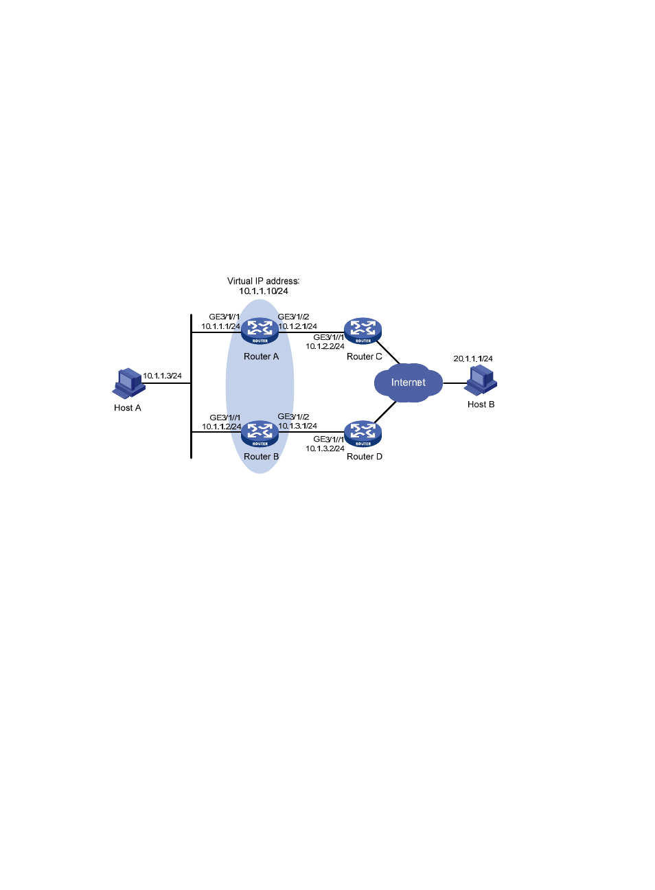
Network requirements
•
As shown in
, Host A needs to access Host B on the Internet. The default gateway of Host
A is 10.1.1.10/24.
•
Router A and Router B belong to VRRP group 1, whose virtual IP address is 10.1.1.10.
•
When Router A works normally, packets from Host A to Host B are forwarded through Router A.
When VRRP detects that a fault is on the uplink interface of Router A through the interface
management module, packets from Host A to Host B are forwarded through Router B.
Figure 38 Network diagram
Configuration procedure
1.
Configure the IP address of each interface as shown in
2.
Configure a track entry on Router A:
# Configure track entry 1, and associate it with the physical status of the uplink interface
GigabitEthernet 3/1/2.
[RouterA] track 1 interface GigabitEthernet 3/1/2
3.
Configure VRRP on Router A:
# Create VRRP group 1, and configure the virtual IP address 10.1.1.10 for the group.
[RouterA] interface GigabitEthernet 3/1/1
[RouterA-GigabitEthernet3/1/1] vrrp vrid 1 virtual-ip 10.1.1.10
# Set the priority of Router A in VRRP group 1 to 110.
[RouterA-GigabitEthernet3/1/1] vrrp vrid 1 priority 110
# Configure to monitor track entry 1 and specify the priority decrement as 30.
[RouterA-GigabitEthernet3/1/1] vrrp vrid 1 track 1 reduced 30
4.
Configure VRRP on Router B:
[RouterB] interface GigabitEthernet 3/1/1
# Create VRRP group 1, and configure the virtual IP address 10.1.1.10 for the group.
[RouterB-GigabitEthernet3/1/1] vrrp vrid 1 virtual-ip 10.1.1.10