Configuration procedure, Verifying the configuration – H3C Technologies H3C S5560 Series Switches User Manual
Page 62
47
0030-3030-662e-6532-3030-2e30-3030-322d-4574-6865-726e-6574.
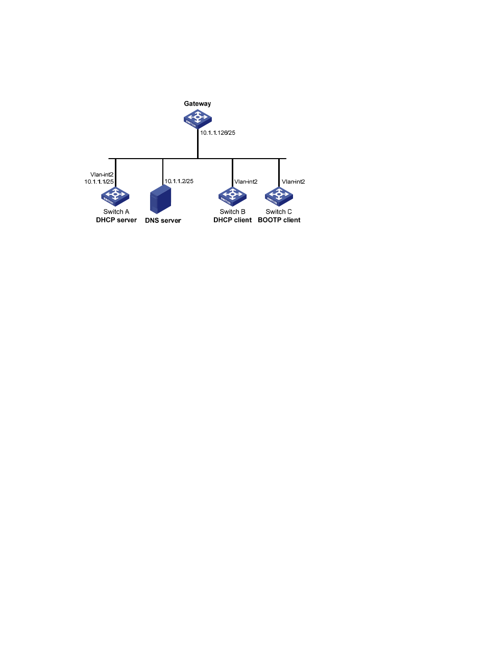
The MAC address of VLAN-interface 2 on Switch C is 000f-e200-01c0.
Figure 16 Network diagram
Configuration procedure
1.
Specify an IP address for VLAN-interface 2 on Switch A:
[SwitchA] interface vlan-interface 2
[SwitchA-Vlan-interface2] ip address 10.1.1.1 25
[SwitchA-Vlan-interface2] quit
2.
Configure the DHCP server:
# Enable DHCP.
[SwitchA] dhcp enable
# Enable the DHCP server on VLAN-interface 2.
[SwitchA] interface vlan-interface 2
[SwitchA-Vlan-interface2] dhcp select server
[SwitchA-Vlan-interface2] quit
# Create DHCP address pool 0.
[SwitchA] dhcp server ip-pool 0
# Configure a static binding for DHCP client switch B.
[SwitchA-dhcp-pool-0] static-bind ip-address 10.1.1.5 25 client-identifier
0030-3030-662e-6532-3030-2e30-3030-322d-4574-6865-726e-6574
# Configure a static binding for Switch C.
[SwitchA-dhcp-pool-0] static-bind ip-address 10.1.1.6 25 hardware-address
000f-e200-01c0
# Specify the DNS server and gateway.
[SwitchA-dhcp-pool-0] dns-list 10.1.1.2
[SwitchA-dhcp-pool-0] gateway-list 10.1.1.126
[SwitchA-dhcp-pool-0] quit
[SwitchA]
Verifying the configuration
# Verify that Switch B can obtain IP address 10.1.1.5 and all other network parameters from Switch A.
(Details not shown.)