Configuration example, Network requirements, Configuration procedure – H3C Technologies H3C S5560 Series Switches User Manual
Page 238
223
Step Command
Remarks
4.
Configure a source address or
source interface for the tunnel
interface.
source { ip-address |
interface-type interface-number }
By default, no source address or
source interface is configured for
the tunnel interface.
The specified source address or the
IPv6 address of the specified source
interface is used as the source IP
address of tunneled packets.
5.
Configure a destination
address for the tunnel
interface.
destination ip-address
By default, no destination address
is configured for the tunnel
interface.
The tunnel destination address must
be the IP address of the receiving
interface on the tunnel peer. It is
used as the destination IP address
of tunneled packets.
6.
(Optional.) Set the DF bit for
tunneled packets.
tunnel dfbit enable
By default, the DF bit is not set for
tunneled packets.
Configuration example
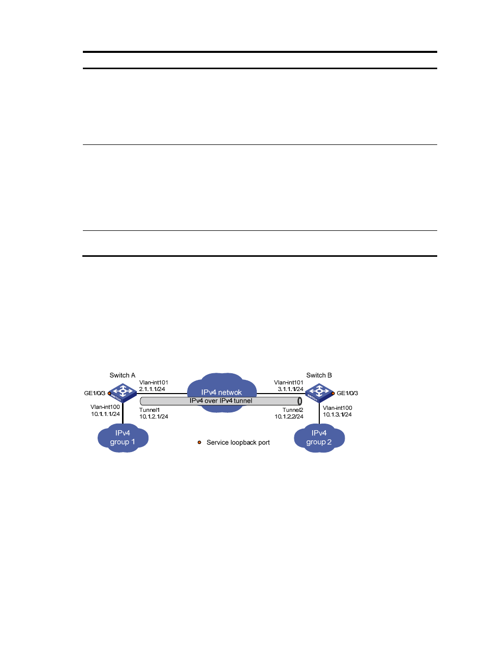
Network requirements
As shown in
, the two subnets IPv4 group 1 and IPv4 group 2 use private IPv4 addresses.
Configure an IPv4 over IPv4 tunnel between Switch A and Switch B so the two subnets can reach each
other.
Figure 90 Network diagram
Configuration procedure
Make sure Switch A and Switch B have the corresponding VLAN interfaces created and can reach each
other through IPv4.
1.
Configure Switch A:
# Specify an IPv4 address for VLAN-interface 100.
[SwitchA] interface vlan-interface 100
[SwitchA-Vlan-interface100] ip address 10.1.1.1 255.255.255.0
[SwitchA-Vlan-interface100] quit
# Specify an IPv4 address for VLAN-interface 101, which is the physical interface of the tunnel.
[SwitchA] interface vlan-interface 101