Configuration example, Network requirements, Requirements analysis – H3C Technologies H3C S5560 Series Switches User Manual
Page 232: Configuration procedure
217
Configuration example
Network requirements
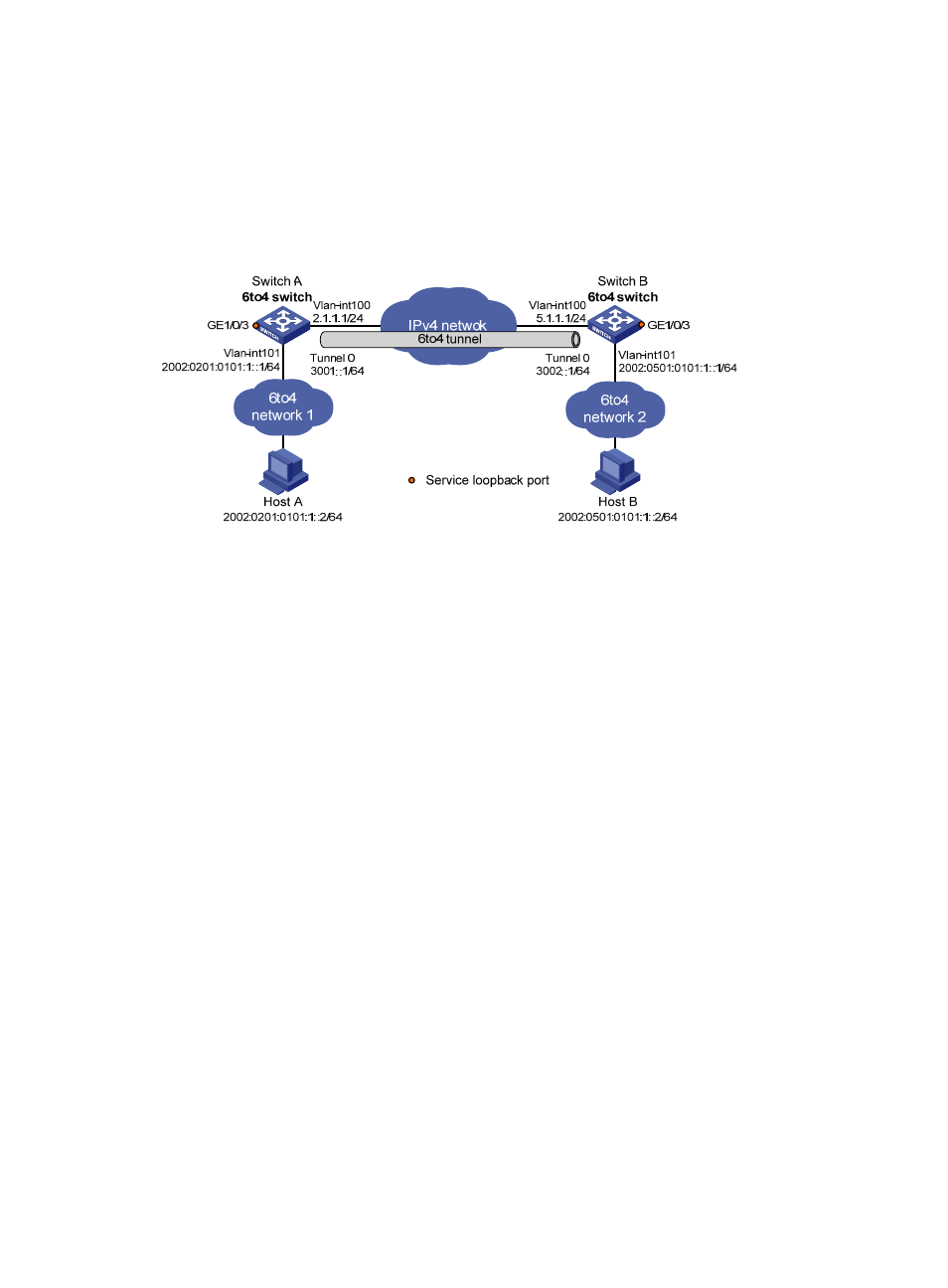
As shown in
, configure a 6to4 tunnel between 6to4 switches Switch A and Switch B so Host
A and Host B can reach each other over the IPv4 network.
Figure 88 Network diagram
Requirements analysis
To enable communication between 6to4 networks, configure 6to4 addresses for 6to4 switches and hosts
in the 6to4 networks.
•
The IPv4 address of VLAN-interface 100 on Switch A is 2.1.1.1/24, and the corresponding 6to4
prefix is 2002:0201:0101::/48. Host A must use this prefix.
•
The IPv4 address of VLAN-interface 100 on Switch B is 5.1.1.1/24, and the corresponding 6to4
prefix is 2002:0501:0101::/48. Host B must use this prefix.
Configuration procedure
Make sure Switch A and Switch B have the corresponding VLAN interfaces created and can reach each
other through IPv4.
1.
Configure Switch A:
# Specify an IPv4 address for VLAN-interface 100.
[SwitchA] interface vlan-interface 100
[SwitchA-Vlan-interface100] ip address 2.1.1.1 24
[SwitchA-Vlan-interface100] quit
# Specify a 6to4 address for VLAN-interface 101.
[SwitchA] interface vlan-interface 101
[SwitchA-Vlan-interface101] ipv6 address 2002:0201:0101:1::1/64
[SwitchA-Vlan-interface101] quit
# Create service loopback group 1 and specify its service type as tunnel.
[SwitchA] service-loopback group 1 type tunnel
# Assign GigabitEthernet 1/0/3 to service loopback group 1.
[SwitchA] interface GigabitEthernet 1/0/3
[SwitchA-GigabitEthernet1/0/3] port service-loopback group 1