Configuration procedure – H3C Technologies H3C S5560 Series Switches User Manual
Page 257
242
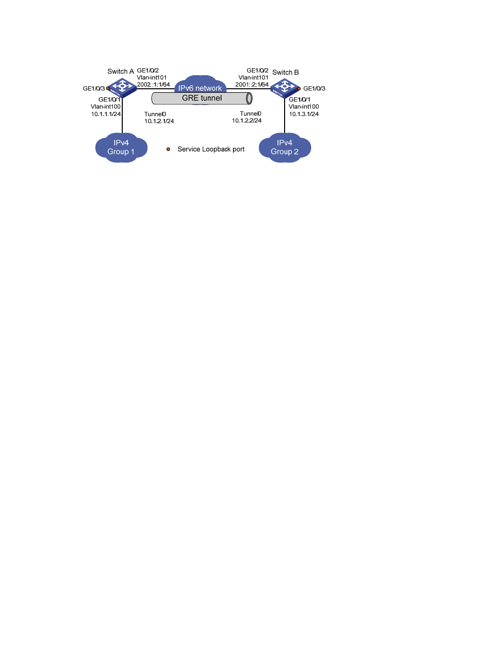
Figure 96 Network diagram
Configuration procedure
Before performing the following configuration, configure an IP address for each interface, and make sure
Switch A and Switch B can reach each other.
1.
Configure Switch A:
# Create service loopback group 1, and configure the service type as tunnel.
[SwitchA] service-loopback group 1 type tunnel
# Add port GigabitEthernet1/0/3 to service loopback group 1.
[SwitchA] interface GigabitEthernet 1/0/3
[SwitchA-GigabitEthernet1/0/3] port service-loopback group 1
[SwitchA-GigabitEthernet1/0/3] quit
# Create a tunnel interface Tunnel 0, and specify the tunnel mode as GRE over IPv6.
[SwitchA] interface tunnel 0 mode gre ipv6
# Configure an IP address for the tunnel interface.
[SwitchA-Tunnel0] ip address 10.1.2.1 255.255.255.0
# Configure the source address of the tunnel interface as the IPv6 address of VLAN-interface 101
on Switch A.
[SwitchA-Tunnel0] source 2002::1:1
# Configure the destination address of the tunnel interface as the IPv6 address of VLAN-interface
101 on Switch B.
[SwitchA-Tunnel0] destination 2001::2:1
[SwitchA-Tunnel0] quit
# Configure a static route from Switch A through the tunnel interface to Group 2.
[SwitchA] ip route-static 10.1.3.0 255.255.255.0 tunnel 0
2.
Configure Switch B:
# Create service loopback group 1, and configure the service type as tunnel.
[SwitchB] service-loopback group 1 type tunnel
# Add port GigabitEthernet1/0/3 to service loopback group 1.
[SwitchB] interface GigabitEthernet 1/0/3
[SwitchB-GigabitEthernet1/0/3] port service-loopback group 1
[SwitchB-GigabitEthernet1/0/3] quit
# Create a tunnel interface Tunnel 0, and specify the tunnel mode as GRE over IPv6.
[SwitchB] interface tunnel 0 mode gre ipv6