Configuration example, Network requirements, Configuration procedure – H3C Technologies H3C S5560 Series Switches User Manual
Page 241
226
Step Command
Remarks
4.
Configure the source
address or interface for
the tunnel interface.
source { ipv6-address |
interface-type interface-number }
By default, no source address or interface
is configured for the tunnel.
The specified source address or the
primary IPv6 address of the specified
source interface is used as the source IPv6
address of tunneled packets.
5.
Configure the
destination address for
the tunnel interface.
destination ipv6-address
By default, no destination address is
configured for the tunnel.
The tunnel destination address must be
the IPv6 address of the receiving interface
on the tunnel peer. It is used as the
destination IPv6 address of tunneled
packets.
Configuration example
Network requirements
As shown in
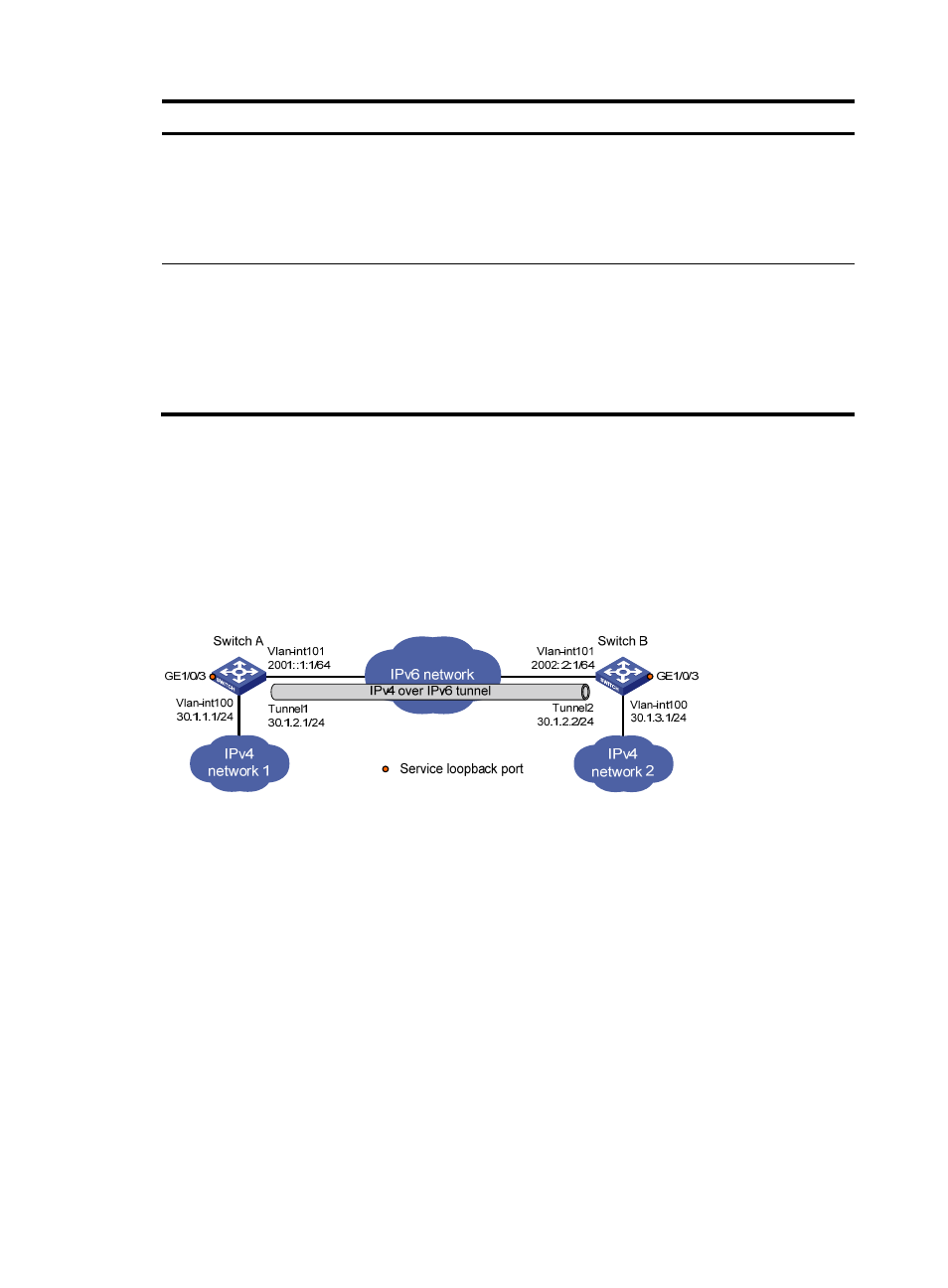
, configure an IPv4 over IPv6 tunnel between Switch A and Switch B so the two IPv4
networks can reach each other over the IPv6 network.
Figure 91 Network diagram
Configuration procedure
Make sure Switch A and Switch B have the corresponding VLAN interfaces created and can reach each
other through IPv6.
1.
Configure Switch A:
# Specify an IPv4 address for VLAN-interface 100.
[SwitchA] interface vlan-interface 100
[SwitchA-Vlan-interface100] ip address 30.1.1.1 255.255.255.0
[SwitchA-Vlan-interface100] quit
# Specify an IPv6 address for VLAN-interface 101, which is the physical interface of the tunnel.
[SwitchA] interface vlan-interface 101
[SwitchA-Vlan-interface101] ipv6 address 2001::1:1 64
[SwitchA-Vlan-interface101] quit
# Create service loopback group 1 and specify its service type as tunnel.
[SwitchA] service-loopback group 1 type tunnel