Amer Networks SS2GD8I User Manual
Page 13
7
The following table lists the types of fiber supported by the switch:
Multi-mode Fiber Cable and Modal Bandwidth
Multi-mode 62.5/125μm Multi-mode
50/125μm
Modal Bandwidth
Distance
Modal Bandwidth Distance
160MHz-km 220m 400MHz-km 500m
IEEE 802.3z Gigabit
Ethernet 1000SX 850nm
200MHz-km 275m 500MHz-km 550m
Single-mode Fiber 9/125μm
Single-mode transceiver 1310nm 10km
1000Base-
LX/LHX/XD/ZX
Single-mode transceiver 1550nm 30, 50km
TX(Transmit) 1310 nm
Single-Mode 20km
RX(Receive) 1550 nm
TX(Transmit) 1550 nm
1000Base-LX Single
Fiber (BIDI LC)
Single-Mode 20km
RX(Receive) 1310 nm
Table 2-1: Cable Types
Typical Network Topologies
A network with the lowest number of levels of switches will reduce the timing delay between server and
client. With this approach, the number of switches in any one path will be minimized, lowering the
possibility of a network loop and improving network efficiency. If more than two switches are connected in
the same network, select one switch as the Level 1 switch and connect all other switches to it at Level 2.
It is recommended to connect the servers to the Level 1 switch. This is a general case if no VLANs or
other special requirements are applied.
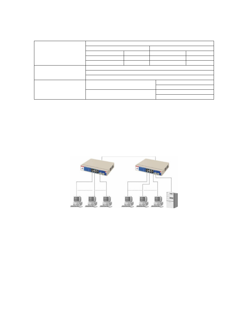
Case 1: All ports are in the same local area network. Every port can access each other (See Figure 2-3).
Figure 2-3 No VLAN Configuration Diagram
If VLANs are enabled and configured, each node in the network can only communicate with other nodes
in the same VLAN.
Here VLAN area is defined by what VLAN you are using. The switch supports both port-based VLAN and
tag-based VLAN. They are different in practical deployment, especially in terms of physical location. The
following diagram shows how each on works and the differences between the two.