10/100 ethernet, Ethernet led indicators, Network interfaces – Verilink T1 Access Router (34-00327) Product Manual User Manual
Page 22: 10/100 ethernet -8, Ethernet led indicators -8, Network interfaces -8
1-8
T 1 A c c e s s R o u t e r
These diagnostic messages can disrupt the connected device; however, you
can configure the unit to disable their transmission.
NOTICE:
For information on pinout assignments for this connector, refer to
Supervisory Port Pin Assignments on page A-5. See Ordering
Information on page A-4 for information on cables for this connector.
10/100 Ethernet
The T1 Access Router provides one
10/100 ETHERNET
interface. This
interface is an eight-pin modular jack that complies with standard
twisted-pair, 10/100Base-T requirements. The 10/100Base-T cable is supplied
by the end user. Refer to Ethernet Connection Pin Assignments on page A-5
for pin assignments and cable descriptions.
Ethernet LED Indicators
There are two unlabeled indicator LEDs on either side of the
10/100 ETHERNET
jack. The LED on the left side of the jack pulses amber to
indicate data activity (either transmit or receive). The LED on the right side of
the jack lights green to indicate that the link layer is operational.
Network Interfaces
Labeled on the rear panel of the T1 Access Router as
NET
, this interface’s
connection is a standard RJ-48C, eight -pin modular jacks that contain an
automatic line build out (ALBO). The ALBO allows the unit to be located a
substantial distance away from the telco network interface with a receive
signal level to
−
27 dB. This interface operates in either long-haul or
short-haul mode.
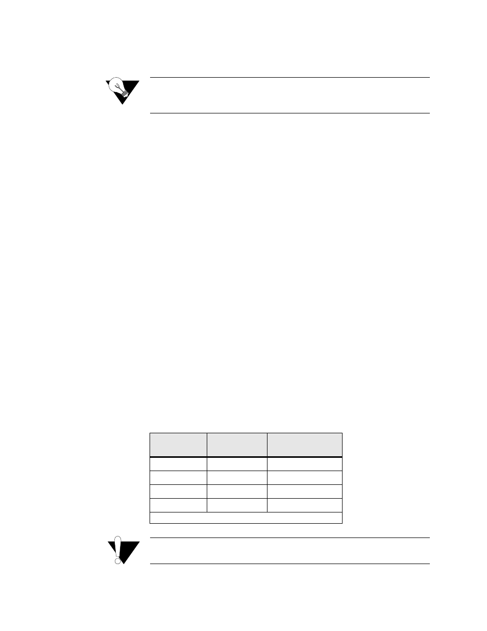
The Network interface transmit LBO level should be set as instructed in the
Line Build-out parameters section on page 3-5. Maximum suggested cable
lengths for the connection from the unit to the network are listed in the table
below. Calculations are based on a cable temperature of 70
°
F, 0.083
µ
F/ mile
capacitance, a 27-dB loss, and a 100-
Ω
, non-loaded, twisted-pair cable.
CAUTION:
In accordance with FCC Rules, Part 68.218(b), you must notify the
telephone company prior to disconnecting this product.
Cable Type
Loss per 1000 ft
(dB)
Max Cable Length
(ft)
26-gauge PIC
6.8
4,400
24-gauge PIC
5.4
5,500
22-gauge PIC
4.2
7,100
19-gauge PIC
3.0
10,000
(PIC - Plastic Insulated Cable)