Rear panel connections, Supervisory port, Rear panel connections -7 – Verilink T1 Access Router (34-00327) Product Manual User Manual
Page 21: Supervisory port -7
A b o u t t h e T 1 A c c e s s R o u t e r
1-7
The user-activated input control buttons on the T1 Access Router are
described in the following table.
*The
CONFIG
button must be held until the
MODE
LED lights amber and remains illuminated for the
default configuration to take effect.
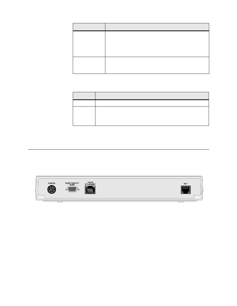
Rear Panel Connections
The rear panel of the T1 Access Router has four connectors
−
POWER
,
SUPERVISORY PORT
,
10/100 ETHERNET
, and
NET
−
below.
Figure 1.2
T1 Access Router Rear Panel
The following paragraphs describe the T1 Access Router connectors.
Supervisory Port
The
SUPERVISORY PORT
on the T1 Access Router is a DB-9 female DCE
connector configured for 8 bits, no parity, and 1 stop bit. Bit rates are
configured through the Web server (see Supervisory on page 3-13) or VT100
interface. The Supervisory port speed can be set to 1200, 2400, 4800, 9600,
19200, 38400, 57600, 115200 bps. The initial default rate of the Supervisory
port is 19200 bps.
On power-up, the Supervisory port sends out diagnostic messages at the bit
rate of 115.2 kbps until the Supervisory service acquires the Supervisory port.
ALARM
The
ALARM
indicator is off (not illuminated) when no alarm
conditions exist.
The indicator lights amber to indicate an OOF alarm. (Other
alarms may also be active.)
The indicator lights red for all other alarm conditions.
POWER
The indicator lights green when power is applied to the unit.
The indicator lights amber in test modes (port looped or BERT
active).
Button
Description
RESET
The
RESET
button provides a hardware reset to the unit.
CONFIG
The
CONFIG
button sets the unit back to its factory default
configuration for Packet Mode operation; this is the same as a
maintenance reset. To initiate this function, you must press and hold
the
CONFIG
button during a power-up sequence.*
Indicator
Description