Verilink T1 Access Router (34-00327) Product Manual User Manual
Page 157
V T 1 0 0 I n t e r f a c e
4-49
Figure 4.41
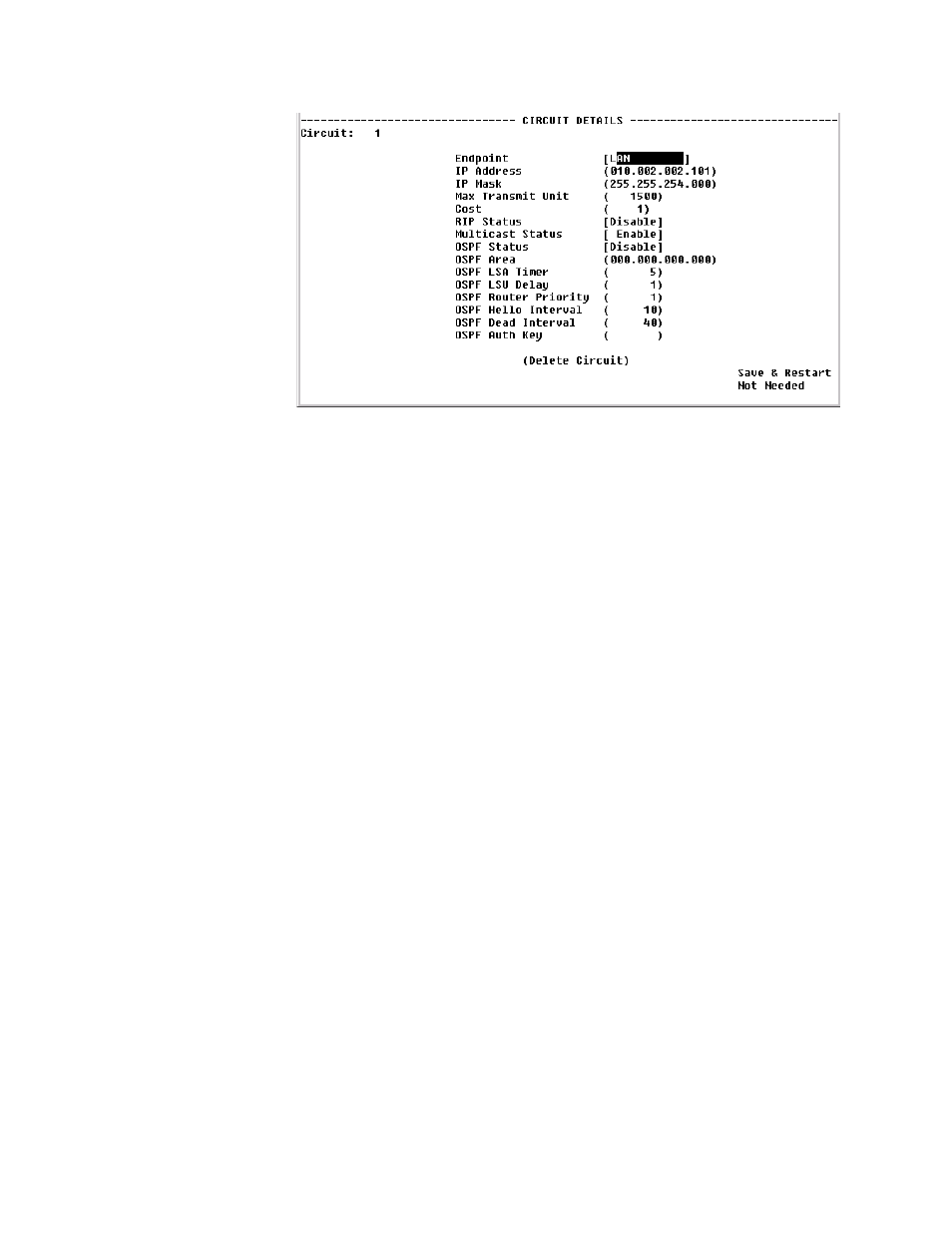
Circuit Details Screen
Endpoint
Endpoint name. By default, the first circuit is always the LAN circuit. All
other circuits are associated with Endpoint names as defined in the Endpoint
Table. (See Endpoint Table Screen shown on page 4-29).
IP Address
IP Address of the circuit.
IP Mask
IP mask of the circuit.
Max Transmit Unit
Maximum transmit unit this circuit will send at any one time.
Cost
Represents the relative time of treatment of an IP packet. This value is used
when there are multiple routes to the same destination. When two or more
routes are available, the one with the lowest circuit cost is selected. A frame
relay circuit should have a higher value than a LAN circuit.
RIP Status
Indicates whether or not RIP is enabled on this circuit.
Values: Enable, Disable
Default: Enable
Multicast Status
Indicates whether or not Multicast is enabled on this circuit.
Values: Enable, Disable
Default: Enable
OSPF Status
Indicates whether or not OSPF is enabled on this circuit.
Values: Enable, Disable
Default: Enable
OSPF Area
Represents that area that this circuit is part of.
OSPF LSA Timer
Determines how often The Link State Acknowledgment (LSA) packet is sent.
Values: 1
−
3600
Default: 5