Table 3-17 – Verilink DPRI 2922 (880-503142-001) Product Manual User Manual
Page 57
Configuring the DPRI 2922 Via the NCM 2000 Craft Interface
Verilink DPRI 2922
3-27
Table 3-17
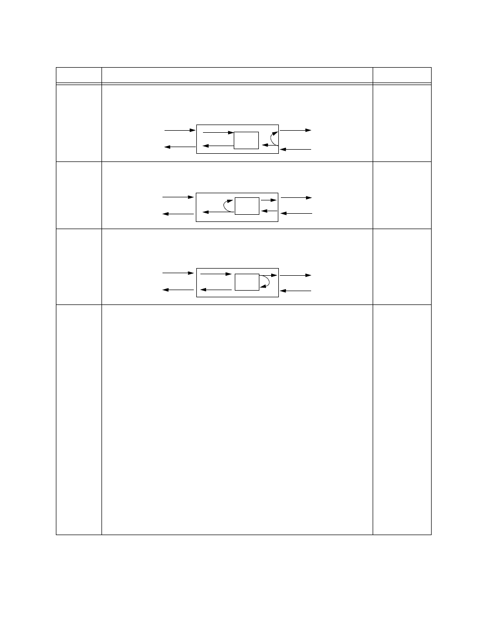
T1 Port Diagnostics Menu Commands
Command
Description
Options
Ln
Line Loopback (LLB): This option tests the network line from the far-end
node. With Line Loopbacks, incoming signals are looped around and sent
back toward the network. The service provider or far-end node administrator
can then determine if the network line is good.
1) DEACTIVATE
2) ACTIVATE
Pn
Payload Loopback (PLB): This option tests the DPRI from the far-end node. In
this case, the data goes through the network line and the DPRI framer before
it is looped back toward the network.
1) DEACTIVATE
2) ACTIVATE
Rn
Local Loopback (RLB): This option tests all of the DPRI. Also known as a
Repeater Loopback, the data sent from the data equipment passes through
the DPRI up to the network interface and back to the equipment without
passing through the network line.
1) DEACTIVATE
2) ACTIVATE
Tn
Test Pattern:
None: This option indicates that no test pattern will be used.
3 in 24: 3-in-24 Onrs test pattern which consists of three pulses in every 24-
bit sequence (10001000 10000000 00000000). This stress test is useful for
testing circuits under extremely low density conditions. This is mostly useful
for T1 AMI.
QRSS: Quasi-Random Signal Sequence that limits the signal to a maximum of
15 zeros that can be transmitted sequentially. These signals contain a
medley of 20-bit words (except for more than 15 consecutive 0s). It repeats
every 1,048,575 bits. Also, it contains high density sequences and low
density sequences, and sequences that change from low density to high
density and vice versa (as defined by ANSI T1.403).
2
20
-1: Tests circuits for equalization and timing. It is the same as QRSS, but
without the 15 zeros restriction.
1/8: This pattern tests the ability of a circuit to support a pattern having the
minimum ones density (containing 7 zeros indicating empty pulses and 1
pulse-1000000). It helps discover a timing recovery problem. This is mostly
useful for T1 AMI.
2
15
-1: This pattern tests circuits for equalization and timing using an
alternate pattern for jitter testing. The pattern repeats every 32,757 bits.
All 0s: This pattern is composed entirely of framed zeros (00000000). It
should only be used in conjunction with B8ZS (a clear channel) for end-to-
end testing. This is mostly useful for T1 B8ZS.
1) NONE
2) 3/24
3) QRSS
4) 2
20
-1
5) 1/8
6) 2
15
-1
7) ALL 0’S
8) 55 OCTET
(Daly)
9) ALL 1’S
DPRI
Framer
CPE
T1
DPRI
Framer
CPE
T1
DPRI
Framer
CPE
T1