Verilink DPRI 2922 (880-503142-001) Product Manual User Manual
Page 19
Quick Set-Up
Verilink DPRI 2922
2-3
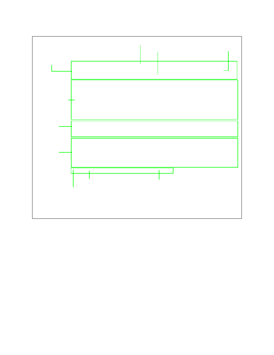
Figure 2-1 NCM Main Menu
-- VERILINK NCM CONTROLLER : FW Rev 4.15, Dec 13 1997 12:53:30 --
Site Name: Verilink Test Access Level: 2
Managing at NEAR end node [127.255.255.0] Node ID: 0
<- SLOT ->
SHELF 1 2 3 4 5 6 7 8 9 10 11 12 13
0 - - - - - - - - - - - - -
1 D *N [A]
2 - - - - - - - - - - - - -
3 - - - - - - - - - - - - -
4 - - - - - - - - - - - - -
KEY: A=DIDCSU, B=DIU/DBU, C=CSU, D=DIU, E=SDIU, F=DIU/DDS, G=DHDM,
H=ATM/IMUX, I=IDCSU, J=PEP, K=DAC, L=HLM, M=IMUX, N=NCM,
Q=QUAD, R=SUBRATE, S=HSM, T=HDM, U=DCSU, V=VCU, X=QPRI
S) shelf/slot O) administration
C) configuration D) diagnostics
P) performance/status A) alarm
B) circuit manager I) manufacturing info
X) exit this screen
A [127.255.255.0] [1,2] DIDCSU 2912 >
Menu Heading Area
Node “Map” (Physical
Location of Modules)
Command List
Firmware Version and Date of Release
Access Level (1-4)
Node Address
Node Address
Data (Command) Entry Area
Module Key
Active NCM Master Designator
❷
❸
❶
❷
❸
❶
Asterisk indicates that the NCM is the Main Controller in the shelf
Indicator for the type of shelf: M= Multi-line, D = Dual-line
Brackets around module letter ( [P] ) indicate current module selected