A.1.1.3 data field, A.1.1.4 error check (checksum) field, A.1.2 exception responses – RLE FDS-Wi V.2.5 User Manual
Page 66: A.2.1 function 03: read output registers, Data field error check (checksum) field, Exception responses, Packet communications for the wireless gateway, Function 03: read output registers, Table a.1, Exception codes
www.rletech.com
66
970.484.6510
A
Modbus Communications
A.1.1.3 Data
Field
The data field of the request is a variable length depending on the function. The data fields for
the Wireless Gateway are 16-bit registers, transmitted high order byte first (big-endian)
A.1.1.4 Error Check (Checksum) Field
The checksum field lets the receiving device determine if the packet has transmission errors.
The Wireless Gateway RTU mode uses a 16-bit cyclic redundancy check (CRC-16).
A.1.2 Exception Responses
If a Modbus master sends an invalid command to the Wireless Gateway or attempts to read an
invalid register, an exception response is generated. The response packet will have the high
order bit of the function code set to one. The data field of the exception response contains the
exception error code.
A.2.
Packet Communications for the Wireless
Gateway
This section outlines the registers with the name and a brief description of each.
A.2.1 Function 03: Read Output Registers
To read the Wireless Gateway parameter values, the master must send a Read Output
Registers request packet.
The Read Output Registers request packet specifies a start register and the number of registers
to read. The start register is numbered from zero (40001 = zero, 40002 = one, etc.).
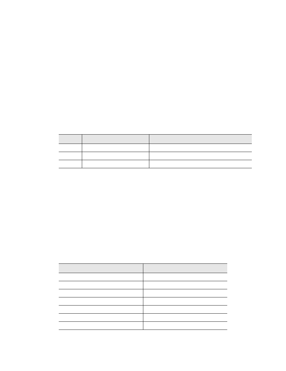
Code
Name
Description
01
Illegal Function
The function code is not supported
02
Illegal Data Address
Attempt to access an invalid address
03
Illegal Data Value
Attempt to set a variable to an invalid value
Table A.1 Exception Codes
Read Registers Request Packet
Read Registers Response Packet
Slave Address (1 byte)
Slave Address (1 byte)
03 (Function code) (1 byte)
03 (Function code) (1 byte)
Start Register (2 bytes)
Byte count (1 byte)
# of registers to read (2 bytes)
First register (2 bytes)
Crc Checksum (2 bytes)
Second register (2 bytes)
…
Crc Checksum (2 bytes)
Table A.2 Read Output Registers Packet Structure