Figure 3.2, Sensor summary sample menu, Table 3.1 – RLE FDS-Wi V.2.5 User Manual
Page 24: Dashboard alarm color codes, Table 3.2, Sensor summary menu options, Sensor summary page
www.rletech.com
24
970.484.6510
3
Web Interface – Standard Version
Sensors on the Dashboard are color coded to help notify users of alarm conditions.
From the homepage, users can also navigate to the Configuration page, edit individual sensor
proprieties, refresh the Wireless Gateway signal, and navigate to the Help page.
3.2. Sensor
Summary
Page
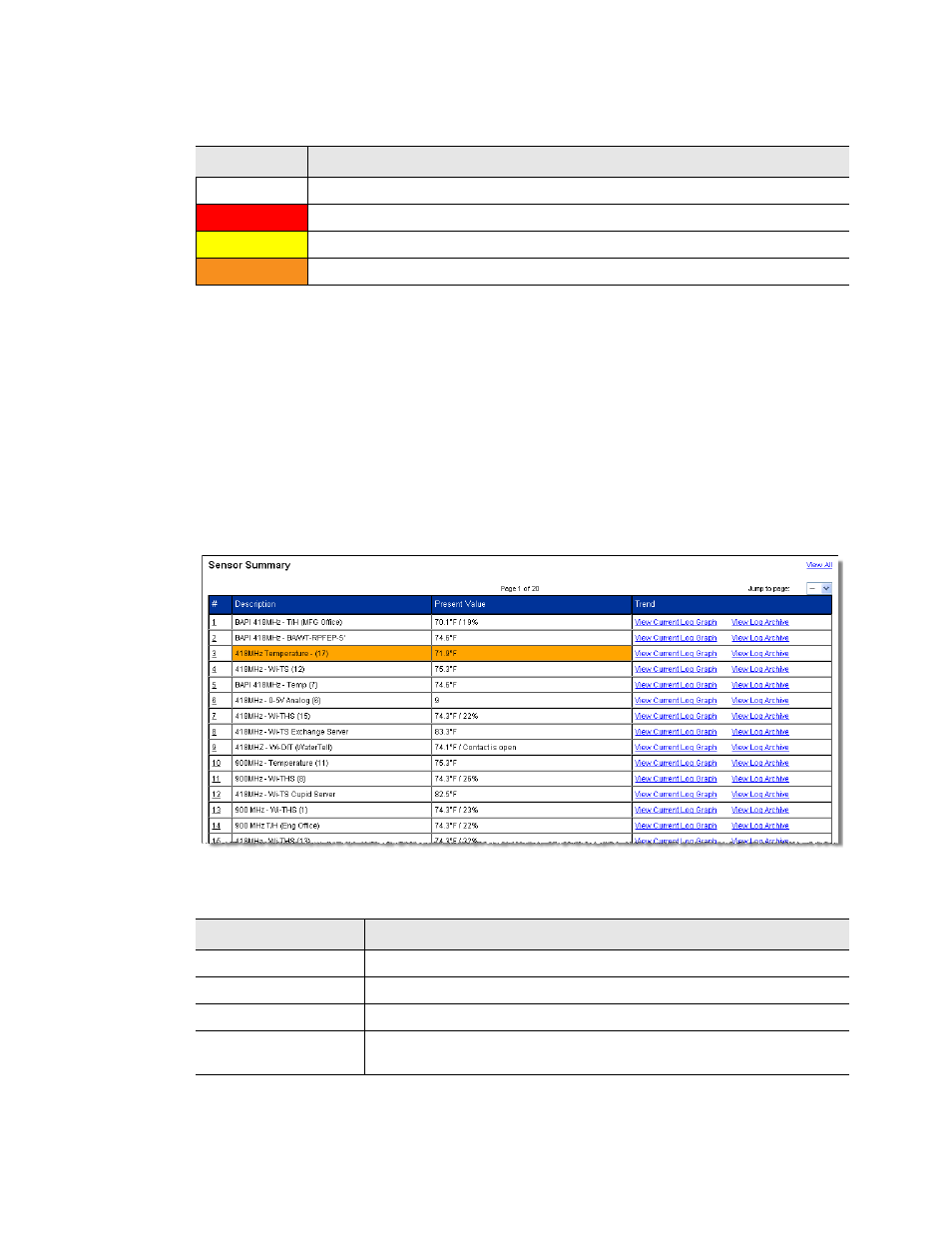
The Sensor Summary page allows users to view all the sensors accessible through the Wireless
Gateway. Up to twenty sensors can be displayed per page, and there are twenty pages
available. The page displays a # link, description, present value and trending information.
Click the number link to access the configuration information for that particular sensor. To
learn more about sensor configuration, reference section 3.6., “Configuration Page - Sensors
Figure 3.2 Sensor Summary Sample Menu
The Current Log Graph link
Color
Indication
No Color
Sensor is registering properly—sensor is communicating properly
Red
Sensor is registering properly—sensor has an analog/digital alarm
Yellow
Sensor is registering properly—sensor has an analog warning
Orange
Sensor is offline—problems with the communications
Table 3.1 Dashboard Alarm Color Codes
Option
Description
# Link
Click on the sensor number to go to the sensor’s configuration page.
Description
A label describing the sensor type and/or location.
Present Value
Displays the current sensor reading.
Trend
Click the links to view either a graph or a log showing the sensor’s
data record from the last 24 hours.
Table 3.2 Sensor Summary Menu Options