Vcm-x / rne setpoints, Vcm-x / rne setpoint screens, Vcm-x / rne operator interfaces technical guide 44 – Orion System VCM-X/RNE Operator Interfaces User Manual
Page 44
VCM-X / RNE SETPOINTS
VCM-X / RNE Operator Interfaces Technical Guide
44
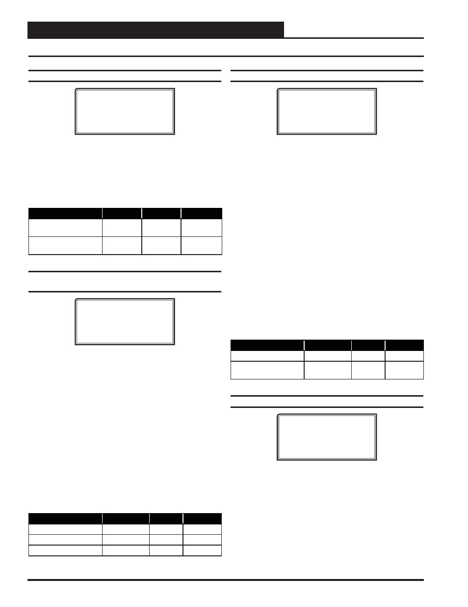
Setpoint Screen #22 - CO
2
Protection Limit
VCM-X / RNE Spts
CO2 Protection Limit
Max Level.: 900 PPM
Reset Rnge: 100 PPM
When the CO
2
level rises above the CO
2
Protection Limit Max Level, the
Economizer’s Minimum Position will begin to reset open proportionally
between the CO
2
Protection Limit Max Level Setpoint and the Reset
Range Setpoint. The Reset Range value is added to the Max Level value.
If the CO
2
levels are equal to or above the Max Level plus the Reset
Range, the Economizer will be opened to its Maximum Economizer
Position if high CO
2
levels occur.
Description
Minimum
Default
Maximum
CO
2
Protection Limit
Max Level
0 PPM
900 PPM
3000 PPM
CO
2
Protection Limit
Reset Range
0 PPM
100 PPM
1500 PPM
Setpoint Screen #23 - Static Setpoint,
Deadband & Control Rate
VCM-X / RNE Spts
Static Spt...: 0.50”
Deadband.....: 0.10”
Control Rate.: 10 s
For VAV units, a Supply Fan VFD or Bypass Damper Actuator is used to
maintain the Duct Static Pressure Setpoint. The Static Pressure Output
Signal varies to control the Static Pressure Setpoint. If the Duct Static
Pressure is above the Static Setpoint plus the Deadband, the Static Pres-
sure Output Signal will be reduced at every Control Rate interval. If the
Static Pressure is below the Static Setpoint minus the Deadband, the
Output signal will be increased at every Control Rate interval.
The Duct Static Pressure Control Output Signal is a non-confi gurable
Direct Acting Signal (0-10 VDC). This can be used to directly connect
to a Supply Fan VFD without any modifi cations.
When you are using a Bypass Damper Actuator to control the Duct
Static Pressure, you must set up the Bypass Damper Actuator or the
Bypass Damper so that it is Reverse Acting in operation. The Output
Signal increases (closes Bypass Damper) if the Duct Static Pressure is
below the Duct Static Pressure Setpoint by the Deadband amount and
the Output Signal decreases (opens Bypass Damper) if the Static Pres-
sure is above the Setpoint by the Deadband amount.
Description
Minimum
Default
Maximum
Static Spt
0.10″ WG
0.50″ WG
3.0″ WG
Deadband
0.10″ WG
0.10″ WG
1.0″ WG
Control Rate
1 Sec
10 Sec
30 Sec
VCM-X / RNE Setpoint Screens
Setpoint Screen #24 - Building Pressure
VCM-X / RNE Spts
Building Pressure
Setpoint....: 0.10”
Deadband....: 0.02”
Direct Acting Control
If an Exhaust Fan Relay is confi gured, when the Building Static Pres-
sure rises above the Building Pressure Setpoint plus the Deadband, the
Exhaust Fan Relay will activate. It will remain on until the Building
Pressure falls below the Building Pressure Setpoint minus the Deadband.
If Modulating Building Pressure is confi gured, when the Building Static
Pressure rises above the Building Pressure Setpoint plus the Deadband,
the Building Pressure Output Signal will increase until the Building
Static Pressure falls within the Deadband. If the Building Static Pres-
sure falls below the Building Pressure Setpoint minus the Deadband, the
Building Pressure Output Signal will decrease until the Building Static
Pressure rises within the Deadband. The Building Pressure Output Signal
is confi gurable for 0-10 or 2-10 VDC. For more detailed operation infor-
mation, see the VCM-X Controller Technical Guide, VCM-X Modular
E-BUS Controller Technical Guide, or RNE Controller Technical Guide
for the complete Building Pressure Control Sequence of Operation.
Reverse Acting Control
The Building Pressure Output Signal remains a Direct Acting 0-10 or
2-10 VDC signal, but the logic is reversed. On a drop in Building Static
Pressure below the Building Pressure Setpoint minus the Deadband, the
Building Pressure Output Signal will increase.
Description
Min.
Default
Max.
Building Pressure Spt
-0.20″ WG
0.10″ WG
0.20″ WG
Building Pressure
Deadband
0.01″ WG
0.02″ WG
0.10″ WG
Setpoint Screen #25 - RAB Damper Factor
VCM-X / RNE Spts
Return Air Bypass
Damper Factor
Setpoint..: 40%
This setpoint is used when your HVAC unit is confi gured for Return
Air Bypass Damper control. The Return Air Bypass Damper Factor
Setpoint is a percentage value that is used to calculate the Return Air
Damper position in relation to the Return Air Bypass Damper position.
This provides a method for adjusting the airfl ow through the Return
Air Bypass Damper.
Increasing this percentage increases the airfl ow through the Return Air
Bypass Damper by causing the Return Air Damper to move further
towards its closed position in relation to the Return Air Bypass Damper
moving towards its open position.