Rne configuration, Rne confi guration screens, Vcm-x / rne operator interfaces technical guide 32 – Orion System VCM-X/RNE Operator Interfaces User Manual
Page 32
RNE CONFIGURATION
VCM-X / RNE Operator Interfaces Technical Guide
32
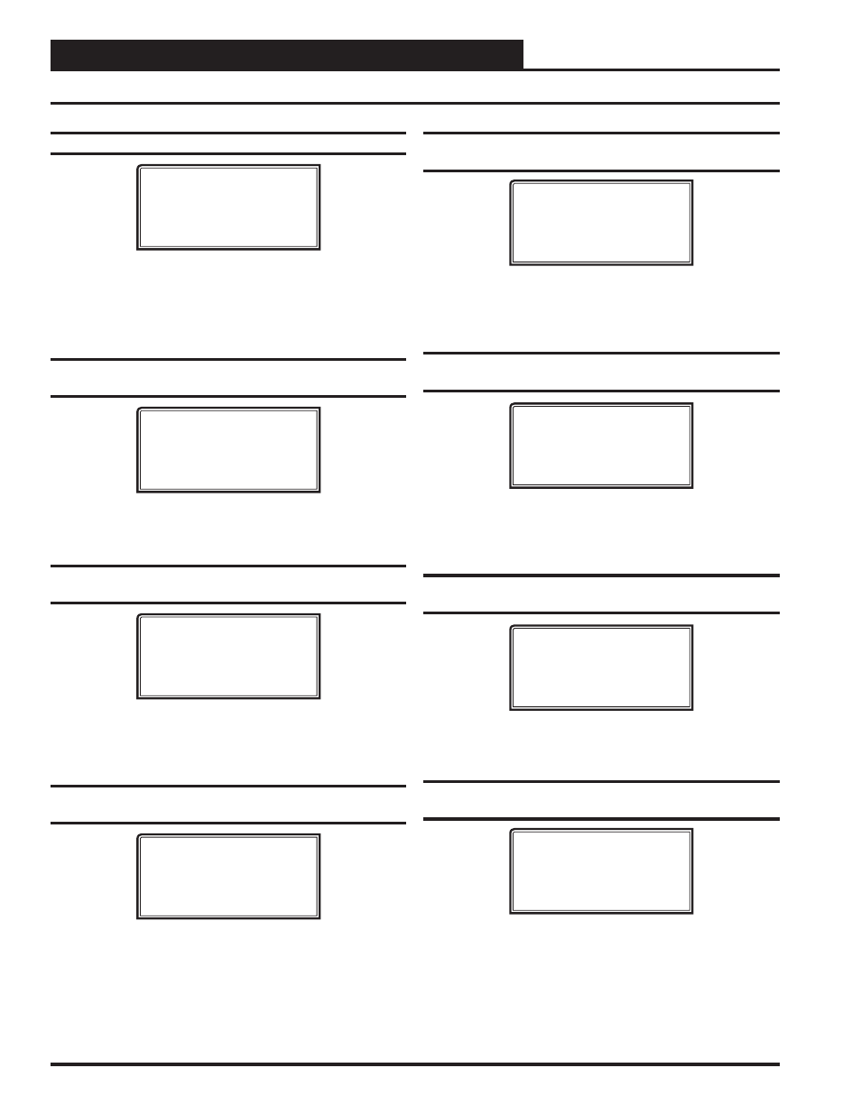
Confi guration Screen #19 - RNE Tonnage
RNE Cnfg ID 101
RNE Tonnage
55–75 Tons
[Press ‘0’ to Change]
Press
<0>
to change/select the desired Tonnage. Default is 55–75 Tons.
The selections are:
55–75 Tons
95–105 Tons
120–140 Tons
Confi guration Screen #20 - Water Source Heat
Pump Installed
RNE Cnfg ID 101
Water Source
Heat Pump: NO
[0=NO 1=YES]
Enter
<1>
for YES if this is a Water Source Heat Pump. Enter
<0>
for
NO. Default is NO.
Confi guration Screen #21 - Modulating Cool-
ing Reverse Acting
RNE Cnfg ID 101
Mod Cooling
Rev Acting: NO
[0=NO 1=YES]
Enter
<1>
for YES if the Modulating Cooling Source requires 0 VDC
to open and 10 VDC to close. You cannot use a Reverse Acting Signal
if a VFD Compressor is being used. Enter
<0>
for NO. Default is NO.
Confi guration Screen #22 - Modulating Cool-
ing Proportional Window
RNE Cnfg ID 101
Mod Cooling
Prop. Window.: 10ºF
Time Period..: 30 s
The Modulating Cooling Proportional Window is the control range of
the Modulating Signal above and below the Active Supply Air Setpoint.
The larger the Modulating Cooling Proportional Window, the smaller
the signal adjustment per Time Period will be for each ºF the supply air
is from the Active Supply Air Temperature Setpoint. The Time Period
is the delay before another signal increase or decrease can be made
and is user-adjustable. Short Time Periods may cause hunting of the
Modulating Signal. Defaults are 10ºF and 30 seconds.
RNE Confi guration Screens
Confi guration Screen #23 - Head Pressure
Module Installed
VCMX-M/HP Cnfg ID 102
Head Pressure
Module Installed: NO
[0=NO 1=YES]
Enter
<1>
for YES if you have a Head Pressure Module installed.
Enter
<0>
for NO. This screen only applies if using the RNE Modular
or WSHP Controller. Default is NO.
Confi guration Screen #24 - Monitor Outdoor
Air CFM
RNE Cnfg ID 101
Monitor Outdoor
Air CFM: NO
[0=NO 1=YES]
Enter
<1>
for YES if you have an Airfl ow Monitoring station measur-
ing the CFM of the Outdoor airfl ow stream of this unit. Enter
<0>
for
NO. Default is NO.
Confi guration Screen #25 - Control Outdoor
Air CFM
RNE Cnfg ID 101
Control Outdoor
Air CFM: NO
[0=NO 1=YES]
Enter
<1>
for YES if you want to control the Outdoor Air Damper to
a CFM setpoint. Enter
<0>
for NO. Default is NO.
Confi guration Screen #26 - Outdoor Duct/
Damper Size
RNE Cnfg ID 101
Outdoor Duct/Damper
Size: 0.00
[Area in sq. ft.]
For the Controller to properly calculate the outside air CFM you need
to enter the inside area (sq. ft.) of the outdoor air duct/damper. When
measuring the outdoor air damper area, be sure to measure the inside
dimensions of the damper. The more accurate the measurements, the
more accurate the CFM reading will be. This value needs to be accurate
to 2 decimal places. Default is 0.00.