Rne configuration, Rne confi guration screens, Vcm-x / rne operator interfaces technical guide – Orion System VCM-X/RNE Operator Interfaces User Manual
Page 31
VCM-X / RNE Operator Interfaces Technical Guide
RNE CONFIGURATION
31
RNE Confi guration Screens
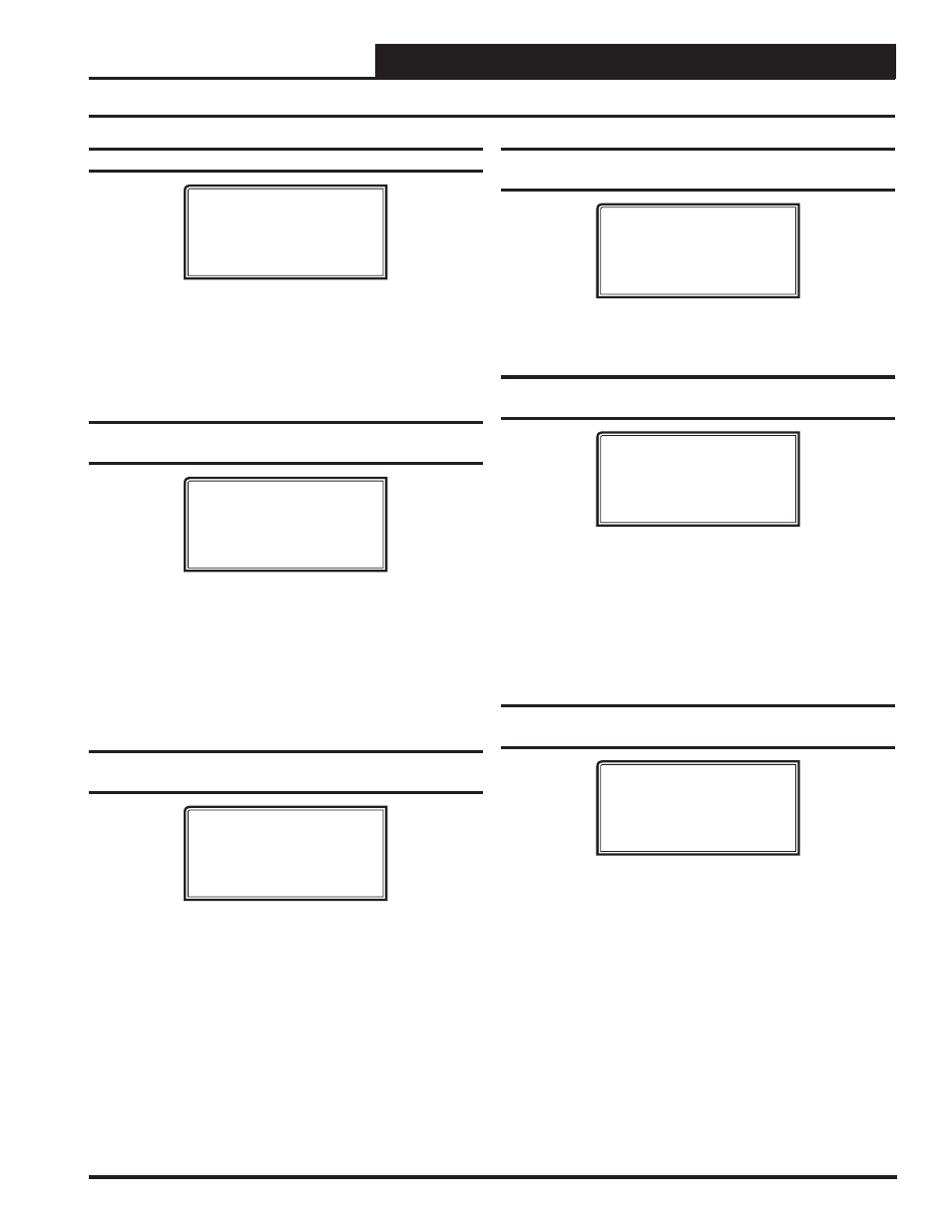
Confi guration Screen #13 - Proof of Flow Input
RNE Cnfg ID 101
Proof Of Flow
Input: NO
[0=NO 1=YES]
Enter
<1>
for YES if the unit is equipped with a Proof of Flow Switch
and it is connected to the RNE. If selected as YES and the Proof of
Flow Switch is open, only the Supply Fan Relay will be active. If any
other relays such as Heating Stages or Cooling Stages are active, they
will be deactivated when the Proof of Flow Switch input is lost. Enter
<0>
for NO. Default is NO.
Confi guration Screen #14 - Modulating Cooling/
Heating
RNE Cnfg ID 101
Mod Cooling: NO
Mod Heating: NO
[0=NO 1=YES]
Enter
<1>
for YES if the HVAC unit is controlling Modulating Heating
or Modulating Cooling or both. If your HVAC unit is going to use a
Modulating Chilled Water Valve or is equipped with a VFD Compressor,
you must select YES for Modulating Cooling. If your HVAC is using a
Modulating Hot Water Valve, Modulating Steam Valve, or a SCR Con-
trolled Electric Heater, you must select YES for Modulating Heating.
This confi guration does not apply to MODGAS using the MODGAS
II Controller. Enter
<0>
for NO. Default is NO.
Confi guration Screen #15 - Modulating
Heating Output Signal
RNE Cnfg ID 101
Mod Heating
Output Signal.: 0
[0=0-10V 1=2-10V]
Enter
<0>
for a 0-10 VDC signal to a Modulating Heat Source such as
a Hot Water Valve or SCR Electric Heater. Enter
<1>
for a 2-10 VDC
signal to a Hot Water Valve or SCR Electric Heater. Default is 0.
Confi guration Screen #16 - Modulating
Heating Reverse Acting
RNE Cnfg ID 101
Mod Heating
Rev Acting: NO
[0=NO 1=YES]
Enter
<1>
for YES if the Modulating Heat Source requires 0 VDC to
open and 10 VDC to close. Enter
<0>
for NO. Default is NO.
Confi guration Screen #17 - Modulating
Heating Proportional Window
RNE Cnfg ID 101
Mod Heating
Prop. Window.: 10ºF
Time Period..: 5 s
The Modulating Heating Proportional Window is the control range of
the Modulating Signal above and below the Active Supply Air Setpoint.
The larger the Modulating Heating Proportional Window, the smaller
the signal adjustment per Time Period will be for each ºF the supply air
is from the Active Supply Air Temperature Setpoint. The Time Period is
the delay before another signal increase or decrease can be made and is
user-adjustable. Short Time Periods may cause hunting of the Modulat-
ing Signal. Defaults are 10ºF and 5 seconds.
Confi guration Screen #18 - Modulating Cooling
Type
RNE Cnfg ID 101
Mod Cooling Type
None
[Press ‘0’ to Change]
Press
<0>
to change/select the desired Modulating Cooling Type. De-
fault is None. The selections are:
None
VFD Half
VFD Full
0-10 VDC CW
2-10 VDC CW