Rne configuration, Rne confi guration screens, Vcm-x / rne operator interfaces technical guide – Orion System VCM-X/RNE Operator Interfaces User Manual
Page 29: Confi guration screens
VCM-X / RNE Operator Interfaces Technical Guide
RNE CONFIGURATION
29
RNE Confi guration Screens
Confi guration Screens
In order to correctly set up the RNE Controller, you must fi rst confi gure
several parameters in regard to the type of HVAC unit and system you
have installed. Most of these values and operating parameters are only
set once at the initial system setup and are never changed.
No matter what screen or menu you’re in, press
.
The Unit Selection Screen will appear, requesting that you enter the
unit ID number.
Unit Selection
Enter Unit ID#
Selected ID#: XXXX
Enter the correct unit ID number of the RNE Controller you want to
confi gure and press
. You will then see Unit Confi guration
Screen #1.
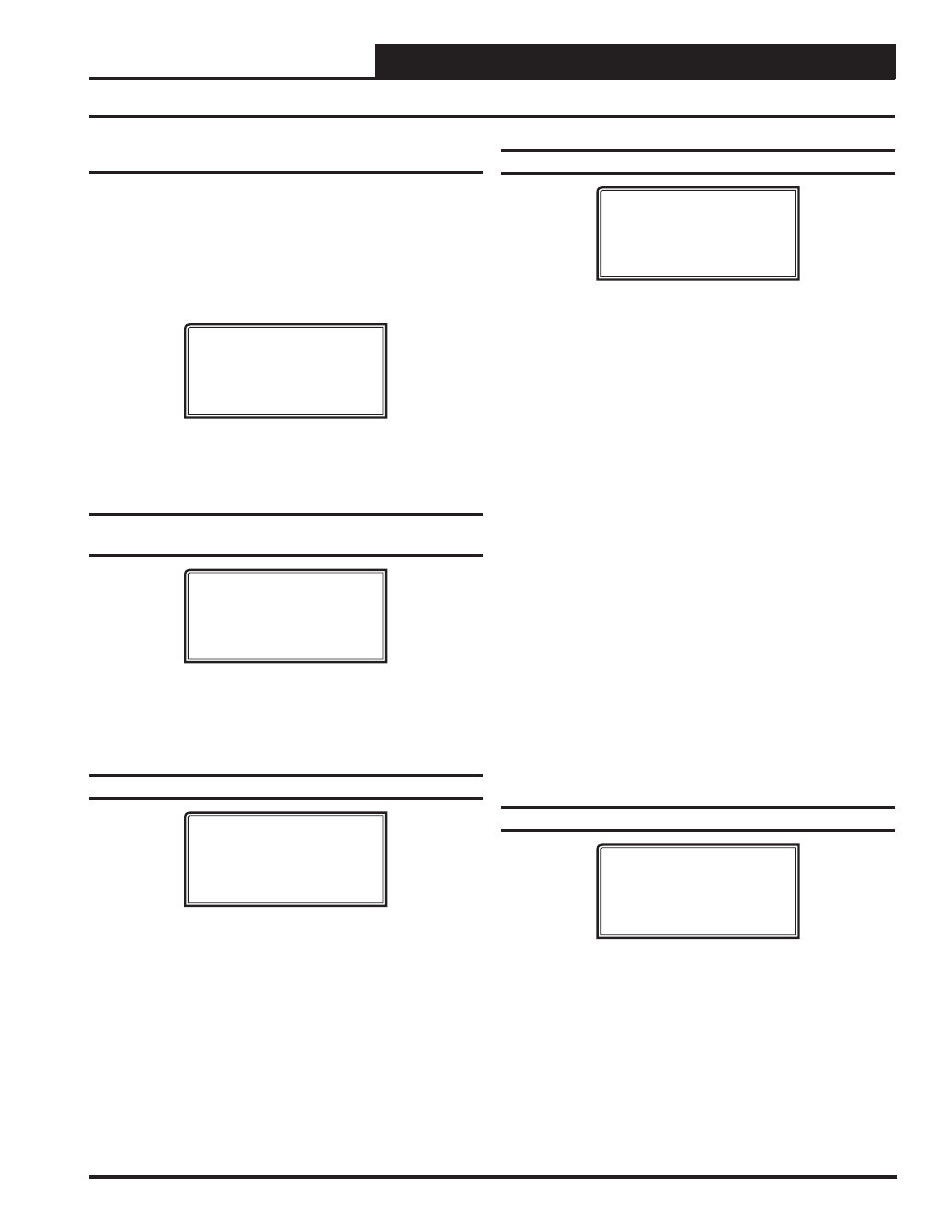
Confi guration Screen #1 - Duct Static
Pressure
RNE Cnfg ID 101
Duct Static Pressure
Control: YES
[0=NO 1=YES]
If the HVAC unit has a Supply Fan that delivers a Constant Volume of
air, enter
<0>
for NO. If the HVAC unit has a Supply Fan that delivers
a Variable Volume of Air using a VFD or a Bypass Damper, enter
<1>
for YES. Default is YES.
Confi guration Screen #2 - Supply Fan Cycle
RNE Cnfg ID 101
Supply Fan Cycle
Mode: NO
[0=NO 1=YES]
If you want the HVAC unit’s Supply Fan to run during Heating, Cool-
ing, or Dehumidifi cation Modes, enter
<1>
for YES. If you want the
HVAC unit’s Supply Fan to run continuously while in the Occupied
Mode, regardless of the Heating, Cooling, or Dehumidifi cation Modes,
enter
<0>
for NO. Default is NO.
Confi guration Screen #3 - HVAC Mode Enable
RNE Cnfg ID 101
HVAC Mode Enable
Supply Air
Press “0” to Change
Enter
<0>
to select the Temperature Sensor that will determine the Heat-
ing, Cooling, or Vent Mode of operation. The selections are:
Supply Air
This is typical for VAV applications. Occupied Cooling
with
Morning
Warm-up.
Outdoor
Air
This is for 100% Outdoor Air (MUA) units.
Dehumidifi cation utilizes a Dewpoint Calculation if
equipped with an Outdoor Air Humidity Sensor.
Space
Temperature
This is for any unit that conditions a space and is not 100%
Outdoor air. Occupied/Unoccupied Heating, Cooling, and
Vent Modes of operation.
Return
Air
This selection can be used when an Average Building
Temperature (the Return Air Temperature) needs to
determine Heating, Cooling, and Vent Modes of operation.
Supply Air/Tempering
This selection is for VAV “cooling only” applications where
because of cold outdoor temperatures, even at minimum
damper position, you may need to enable heat to maintain
the cooling near its Cooling Supply Air Setpoint. When
heat is enabled during this sequence, it will control to
a non-adjustable setpoint that is 2ºF less than the Cooling
Supply Air Setpoint. Includes a Morning Warm-up
sequence.
Confi guration Screen #4 - HVAC Reset Source
RNE Cnfg ID 101
HVAC Reset Source
No Reset
Press “0” to Change
The Supply Air Heating and Cooling Temperature Setpoints can be reset
using various input sources. Default is No Reset. Press
<0>
to change/
select the desired Reset Source for Supply Air Temperature Reset. The
Single Zone VAV option should be selected in applications where the
Supply Fan VFD speed is reset based on the Space Temperature. If you
select No Reset, then neither the Supply Air Setpoint nor the Supply
Fan VFD Reset will occur. The selections are:
No Reset
Fan VFD Percentage
Sp
ace Sensor
Outdoor Sensor
Return Air Sensor
Single Zone (SZ) VAV
Remote Reset Signal
SZ VAV with CV Heating