Measurement Computing DaqBoard 1000 Series User Manual
Page 61
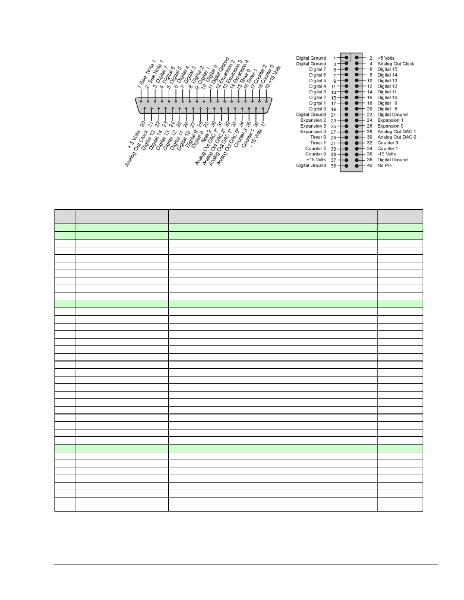
P3 for DaqBoard/2000 Series and /2000c Series Boards Pulse/Frequency/Digital I/O
P3
The P3 DB37
connector is
obtained with
the use of one
of the
following:
DBK201
DBK202
(Note 1)
DBK203
(Note 1)
DBK204
(Note 1)
DBK206
DBK209
Pin
Signal Name
Description for P3 Pin Use
P4
Correlation
1
Digital Ground (Note 1)
Digital Common See Ground Correlation Tables, page 3-15.
⇐
2
Digital Ground (Note 1)
Digital Common See Ground Correlation Tables, page 3-15.
⇐
3
Digital 7
P3 Digital Port Bit 7
B19
4
Digital 6
P3 Digital Port Bit 6
A19
5
Digital 5
P3 Digital Port Bit 5
B20
6
Digital 4
P3 Digital Port Bit 4
A20
7
Digital 3
P3 Digital Port Bit 3
B21
8
Digital 2
P3 Digital Port Bit 2
A21
9
Digital 1
P3 Digital Port Bit 1
B22
10
Digital 0
P3 Digital Port Bit 0
A22
11
Digital Ground
Digital Common See Ground Correlation Tables, page 3-15.
⇐
12
Expansion 2
Reserved
---
13
Expansion 3
Reserved
---
14
Expansion 4
Reserved
---
15
Timer 0
P3 Timer 0 Output
B24
16
Timer 1
P3 Timer 1 Output
A25
17
Counter 2
P3 Counter 2 Input
B28
18
Counter 0
P3 Counter 0 Input
B29
19
+ 15 Volts
Expansion, +15 VDC
B48
20
+ 5 Volt Supply
Expansion, +5 Volt Power
(Refer to Power Management, ch. 2, in DBK Manual)
A1, B1
21
Analog Out Clock
External DAC Pacer Clock Input/Internal DAC Pacer Clock Output
A26
22
Digital 15
Digital I/O; P3 Digital Port Bit 15
B15
23
Digital 14
Digital I/O; P3 Digital Port Bit 14
A15
24
Digital 13
P3 Digital Port Bit 13
B16
25
Digital 12
P3 Digital Port Bit 12
A16
26
Digital 11
P3 Digital Port Bit 11
B17
27
Digital 10
P3 Digital Port Bit 10
A17
28
Digital 9
P3 Digital Port Bit 9
B18
29
Digital 8
P3 Digital Port Bit 8
A18
30
Digital Ground
Digital Common See Ground Correlation Tables, page 3-15.
⇐
31
Analog Out DAC 3 (Note 3)
Analog DAC 3 Output
B50
32
Analog Out DAC 2 (Note 3)
Analog DAC 2 Output
B49
33
Analog Out DAC 1 (Note 3)
Analog DAC 1 Output
A50
34
Analog Out DAC 0 (Note 3)
Analog DAC 0 Output
A49
35
Counter 3
P3 Counter 3 Input
A28
36
Counter 1
P3 Counter 1 Input
A29
37
- 15 Volts
Expansion, - 15 VDC Power
(Refer to Power Management, ch. 2, in DBK
Manual)
A48
Note 1: P3 pins 1 and 2 are not connected on DBK201.
Note 2: For DBK202, DBK203, and DBK204, the 37-pin P3 connector is obtained by connecting a CA-60 cable to an
“On-Board” 40-pin header.
Note 3: Pins 31, 32, 33, and 34 on the P3 DB37 connector are used for Analog Out DACs. DaqBoard/2001, /2003 & /2004 can utilize
all four pins. DaqBoard/2000 does not make use of pins 31 or 32. DaqBoard/2002 and DaqBoard/2005 boards do not make
use of pins 31 through 34 as these series two boards have no Analog Out DAC.
(Note 2)
(Analog Out DAC 3)
(Analog Out DAC 2)
DB37 P3 Connector
Note: There is no direct pin number correlation between the
40-pin header and the DB37 P3 connector.
*
In regard to pins 31 through 34, see Note 3.
DBK202, DBK203, DBK204
“On-Board” 40-Pin Header
The P3 DB37 connector does not apply to DBK200, DBK205, DBK207, DBK207/CJC, or DBK208.
DaqBoard/1000 and /2000 User’s Manual
898195
Connections & Pinouts, DaqBoard/2000 Series 3-11