Connections – Measurement Computing DaqBoard 1000 Series User Manual
Page 36
1-14 Daq Systems and Device Overviews
889094
DaqBoard/1000 and /2000 Series User’s Manual
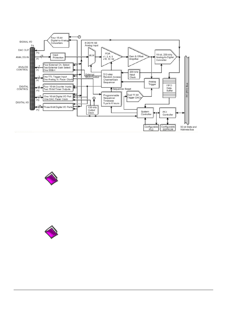
DaqBoard/2001 Block Diagram*
* The DaqBoard/2001c Block Diagram is the same, with exception that the /2001c board uses a
compact-PCI Bus instead of a standard PCI bus.
Connections
Installation
Reference Note: For the DaqBoard/2001 and /2001c installation procedure, refer to either the
DaqBoard/1000 and /2000 Series Installation Guide or to the DaqBoard/2000c Series
Installation Guide, as applicable. The guides are included at the beginning of this manual.
I/O Connector
All input and output signals are available at the board’s 100-pin P4 connector. A 3-foot, 100-conductor
ribbon cable, part number CA-195, mates with connector P4.
Reference Note: There are several P4-connector board options available for connecting the
100 pins of P4 to typical DB37 connectors (P1, P2, and P3). In addition to being briefly
discussed in chapter 3 of this manual, these options, referred to as DBK200 Series, are
detailed in the DBK Cards and Modules User’s Manual (p/n 457-0905).