Synchronous input, Synchronous output, Asynchronous io – Measurement Computing DaqBoard 1000 Series User Manual
Page 28
1-6 Daq Systems and Device Overviews
889094
DaqBoard/1000 and /2000 Series User’s Manual
Expansion Digital I/O
(DaqBoard/2000 Series only)
The DaqBoard/2000 Series boards that have digital I/O capabilities have the ability to expand these
through the P2 port and the connection of applicable digital I/O expansion modules. These modules are
discussed in the DBK
Option Cards & Modules User’s Manual. When using the digital I/O expansion
modules the local P2 Intel 8255 digital I/O becomes inaccessible in lieu of the expansion modules. These
expansion modules provide additionally Intel 8255 ports as well as input isolation for applications that
require the expanded capabilities.
Pulse Stream Output Using Timers
The boards allow the generation of output pulses based upon a programmable setting. These output timers
can be set at any time regardless of the state of any synchronous or asynchronous operations which are
currently taking place on other channels.
Analog Output Channels
The boards that have analog output capabilities have the ability to output analog data to any of the
available (up to four) D/A channels. Each D/A channel may be asynchronously updated by an application
if the D/A channel is not currently being used for waveform output operations.
Counter Input Channels
With exception of DaqBoard/2003, the boards have counter input capabilities and have the ability to read
counter input [if the counter channel is not configured for synchronous acquisition]. As in the case of
synchronous operations the 4 16-bit counter input channels can be used individually or cascaded into two
32-bit counter channels. For either cascaded or non-cascaded counter channels each channel can be
configured for:
•
Clear on Read Mode - specifies that each counter should be cleared (reset to 0) upon being read.
•
Continuous Totalize Mode – specifies that each counter is to free-run and not be cleared during
the read operation.
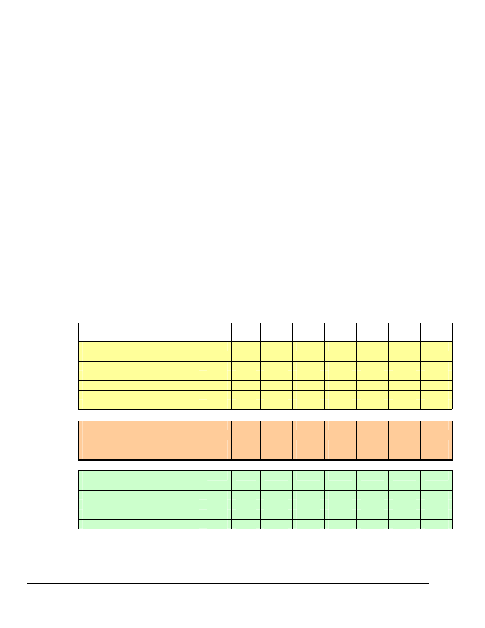
Operation Matrix
*
Operation
1000 1005 2000 2001 2002 2003 2004 2005
Synchronous Input
Analog Main Unit Inputs
Yes
Yes
Yes
Yes
No
No
No
Yes
Analog Expansion Input
No
No
Yes
Yes
No
No
No
Yes
Counter Inputs
Yes
Yes
Yes
Yes
Yes
No
Yes
Yes
Digital Main Unit Inputs
Yes
Yes
Yes
Yes
Yes
No
Yes
Yes
Digital Expansion Inputs
No
No
Yes
Yes
Yes
No
Yes
Yes
Synchronous Output
Analog D/A Waveform Output
Yes
No
Yes
Yes
No
Yes
Yes
No
Streamed Digital Output (16-bit) No
No
Yes
Yes
Yes
No
Yes
Yes
Asynchronous IO
Main Unit Digital I/O
Yes
Yes
Yes
Yes
Yes
No
Yes
Yes
Expansion Digital I/O
No
No
Yes
Yes
Yes
No
Yes
Yes
Timer Output (Pulse Generation)
Yes
Yes
Yes
Yes
Yes
No
Yes
Yes
Analog Output
Yes
No
Yes
Yes
No
Yes
Yes
No
* A similar matrix, intended to highlight board differences at a glance, is presented on page 1-3.