Communication connections, Communication connections -2 – Gasboy Magnetic Card Encoder User Manual
Page 8
Installing MCE
Communication Connections
Page 2-2
MDE-4507 Magnetic Card Encoder User’s Manual · June 2006
Communication Connections
MCE requires the use of a PC for operation. The type of PC used can vary according to the
application and optional printer(s) that may be connected.
Only the authorized Gasboy model encoder hardware, purchased from Gasboy, will work with
this MCE software.
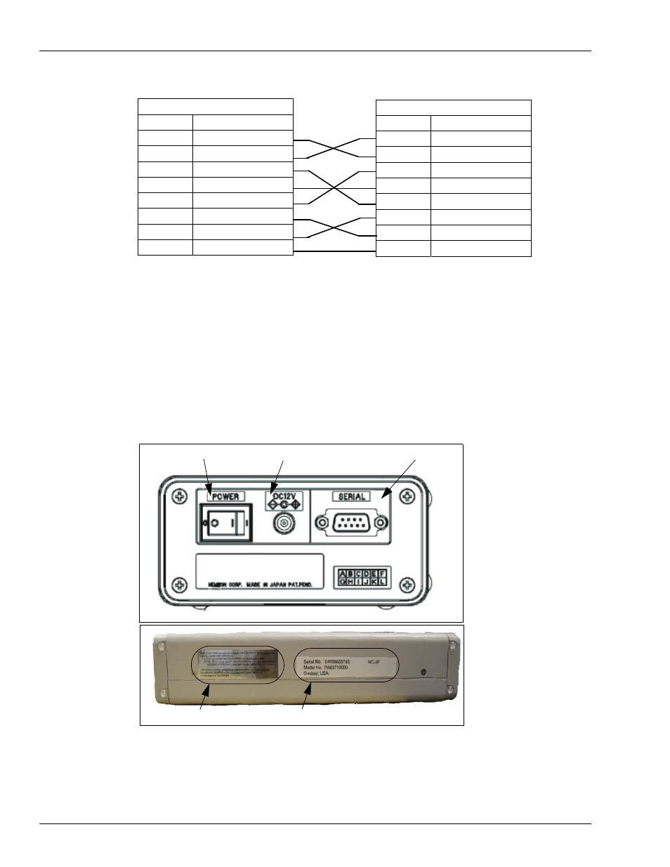
Figure 2-1: Back Panel and Side View of MCE
• Power switch: Power on/off the unit.
• DC Jack: Connect the AC adapter supplied with the unit.
• RS-232 Connector: Connect to Host/PC with the interface cable supplied with the unit.
Note: Turn the power off before connecting the interface cable to the unit.
D-sub-9S (female)
Pin No.
Signal
2 RD
(RxD)
3 SD
(TxD)
4 ER
(DTR)
5 SG
(GND)
6 DR
(DSR)
7 RS
(RTS)
8 CS
(CTS)
Shield FG
D-sub-9S (female)
Pin No.
Signal
2 RD
(RxD)
3 SD
(TxD)
4 ER
(DTR)
5 SG
(GND)
6 DR
(DSR)
7 RS
(RTS)
8 CS
(CTS)
Shield FG
Power Switch
DC Jack
RS-232 Connector
Model number & Serial number
FCC Label