Limitorque actuation systems – Flowserve DDC-100 Master Station II User Manual
Page 39
FCD LMAIM5001-00
DDC-100 Master Station II Installation and Operation Manual
39
Flow Control Division
Limitorque Actuation Systems
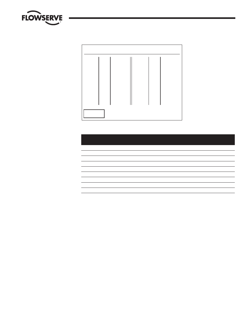
Figure 7-10: The Data Coils screen
Available Coils for each MOV
Coil
Bit
Slave
Number
Number
Address
MX-DDC
UEC-3-DDC
I/O Module
1
0
1
Close / Stop
Close / Stop
Do Not Use
2
1
1
Open / Stop
Open / Stop
Do Not Use
3
2
1
AS-1
Lockout / K3
Relay #3
4
3
1
AS-2
Do Not Use
Relay #4
5
4
1
AS-3
Do Not Use
Relay #5
6
5
1
AS-4
K6
Relay #6
7
6
1
AR-1
Do Not Use
Relay #2
8
7
1
AR-2
Do Not Use
Relay #1
9
8
1
AR-3
Do Not Use
Do Not Use
Touching the “<< Back” button will take the user to the coil selection screen where the chosen coil format
may be saved or altered to another configuration. (Figure 7-9).
Note: Once the selection is made, the “Store” button must be pressed for the configuration to be stored.
Selecting a coil for a specific field unit follows the convention listed below.
DCS Requested Coil = [(field unit address –1) * number of coils per unit] + desired coil
06 —Preset Single Register / 16 —Preset Multiple Register
Presets a value into a single-holding register. (16 Presets a value into multiple-holding registers) The data
table for this function code only permits one or two write registers per field unit. A unique data table is
created starting at register 45001.
Touching the “View/Edit” button for Modbus 06/16 will take the user to a screen similar to Figure 7-12.
This screen permits the user to select the MOV parameters for holding register status.
Data Table Modbus Function Code 05
Coil# MOV# Meaning
0001 1 Close
0002 1 Open
0003 2 Close
0004 2 Open
0005 3 Close
0006 3 Open
0007 4 Close
0008 4 Open
0009 5 Close
0010 5 Open
0011 6 Close
0012 6 Open
Coil# MOV# Meaning
<< Back