Limitorque actuation systems – Flowserve DDC-100 Master Station II User Manual
Page 35
FCD LMAIM5001-00
DDC-100 Master Station II Installation and Operation Manual
35
Flow Control Division
Limitorque Actuation Systems
03 —Read Holding Registers
Reads the binary contents of holding registers in the field units. The Master Station will allow the user to
select the number of registers to be visible per field unit up to a maximum of 10 (registers 4 – 13). Default
setting will display field unit registers 8 and 9.
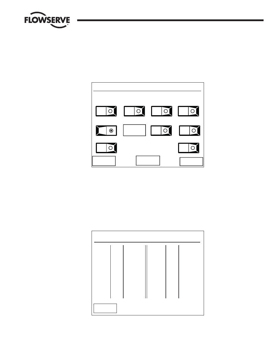
Figure 7-7: The Register Selection screen
When the user selects the register(s) to be mapped into the DCS Data table, the toggle switch will display
a green dot. All registers between the first selected toggle switch and the last toggle switch selected will
be displayed. Once the selections have been completed, touching the “View >>” button will display a
sample Data Table for the first 12 registers (Figure 7-8).
Note: Once the selection is made, the “Store” button must be pressed for the configuration to be
stored.
Figure 7-8: The Sample Data Table screen
Touching the “<< Back” button will take the user to the register selection screen where the chosen register
format may be saved or altered to another configuration. (Figure 7-7).
Data Table Modbus Function Code 03
Reg.# MOV# Meaning
40001 1 Pos
40002 1 Status
40003 2 Pos
40004 2 Status
40005 3 Pos
40006 3 Status
40007 4 Pos
40008 4 Status
40009 5 Pos
40010 5 Status
40011 6 Pos
40012 6 Status
Reg.# MOV# Meaning
<< Back
Modbus Holding Registers
Select Desired Registers/MOV
Torque
Volts
Analog #1 Analog #2
D. out
Fault
Status
Position
DI #1
DI #2
Always
On
Store
View >>
<< Back