Dcs port configuration – Flowserve DDC-100 Master Station II User Manual
Page 31
FCD LMAIM5001-00
DDC-100 Master Station II Installation and Operation Manual
31
Flow Control Division
Limitorque Actuation Systems
7
DCS Port Configuration
7.1
Introduction
DCS Port: includes baud rate for DCS communication, stop bits, parity, electrical standard, DCS address,
RTS ON delay, RTS OFF delay, HMI state during DCS communication traffic, and selectable register maps
for Modbus function code 3, Modbus function code 5/15, and Modbus function code 6/16.
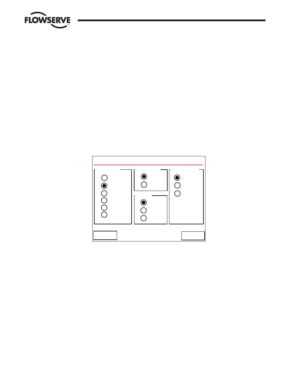
These screens allow the user to configure the DCS port for operation. The first screen presented allows
the user to configure Baud Rate, Retries, Parity, and Electrical connection (Figure 7-1).
Figure 7-1: The Configure DCS Port screen
Touching “Next >>” will take the user to the next DCS Port configuration screen on which the DCS Port
Address, RTS ON Delay, RTS OFF Delay, and HMI control may be disabled when DCS communication
traffic is active (Figure 7-2).
Configure DCS Port
Baud Rate
Stop Bits
Electrical
1
2
RS-232
RS-422
RS-485
None
Even
Odd
Parity
4800
9600
19200
38400
57600
115200
<< Back
Next >>