Pilot relay – Flowserve Logix MD+ ValveSight User Manual
Page 85
ValveSight™ Diagnostics DTM Manual for Logix MD+ Positioner with HART®
FCD-
LGENSF0014-00
© Flowserve Corporation
85
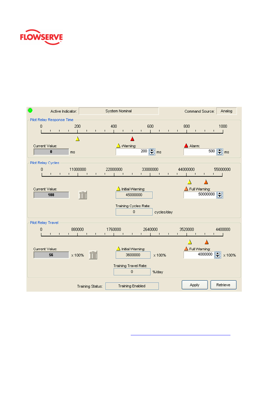
Pilot Relay
The Pilot Relay page shows detailed information about the responsiveness and travel of the
pilot relay. The pilot relay is sometimes called the I/P relay (I to P relay). It converts a
voltage to pneumatic output by controlling a spool or poppet valve. A hall effect sensor
detects the location of the spool or poppet. The controller adjust the location of the spool or
poppet to control the air to the actuator.
Status Area
The Active Indicator area shows the status of the most relevant active indicator. The color
of the "LED light" corresponds to the Active Indicator and the first color of the blink code
sequence on the positioner. Generally green indicates no immediate issues. Yellow
indicates a developing issue. Red indicates the ability to control may be compromised. A
detailed list of the indicators is given in the
Alarm Congfiguraion - Alarm Annunicator
page.
The Command Source field indicates weather the positioner is being controlled by digital or
an analog (4-20 mA) command source.