Analog output calibration – Flowserve Logix MD+ ValveSight User Manual
Page 272
ValveSight™ Diagnostics DTM Manual for Logix MD+ Positioner with HART®
FCD-
LGENSF0014-00
© Flowserve Corporation
272
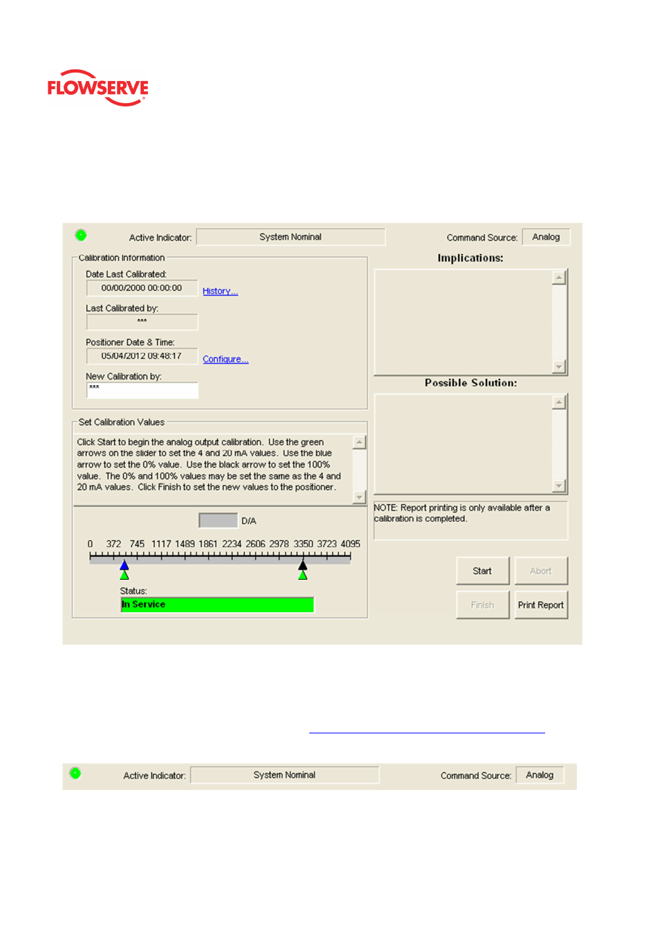
Analog Output Calibration
If the Multi-Function Card (MFC) is configured as an Analog Output, this page allows you to
calibrate the the configuration of the MFC Card to function as an Analog Output.
Status Area
The Active Indicator area shows the status of the most relevant active indicator. The color
of the "LED light" corresponds to the Active Indicator and the first color of the blink code
sequence on the positioner. Generally green indicates no immediate issues. Yellow
indicates a developing issue. Red indicates the ability to control may be compromised. A
detailed list of the indicators is given in the
Alarm Congfiguraion - Alarm Annunicator
page.
The Command Source field indicates weather the positioner is being controlled by digital or
an analog (4-20 mA) command source.
Calibration Information
This area displays information about the last analog output calibration.