Flowserve Logix MD+ ValveSight User Manual
Page 233
ValveSight™ Diagnostics DTM Manual for Logix MD+ Positioner with HART®
FCD-
LGENSF0014-00
© Flowserve Corporation
233
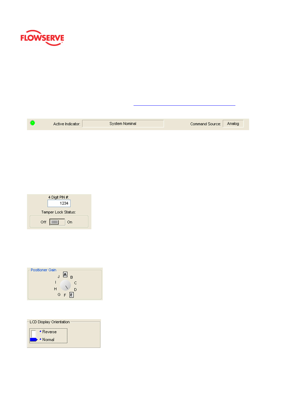
Status Area
The Active Indicator area shows the status of the most relevant active indicator. The color
of the "LED light" corresponds to the Active Indicator and the first color of the blink code
sequence on the positioner. Generally green indicates no immediate issues. Yellow
indicates a developing issue. Red indicates the ability to control may be compromised. A
detailed list of the indicators is given in the
Alarm Congfiguraion - Alarm Annunicator
page.
The Command Source field indicates weather the positioner is being controlled by digital or
an analog (4-20 mA) command source.
Tamper Lock
The
Local Interface
box contains an On/Off switch. In order to prevent unintentional
adjustments of the configuration, tuning, or control of the valve, the Tamper Lock feature
may be used. This is set in the DTM and disables the buttons and menus except for the
ability to view the status of the positioner. When locked, the positioner may be temporarily
unlocked by entering a PIN. (An LCD is required to enter the PIN.) Or, the positioner can be
unlocked from the DTM.
In the 4 Digit PIN # field, enter the PIN. The default PIN is 1234.
Click the Tamper Lock Status switch to activate or deactivate the tamper lock feature.
Positioner Gain
View the position of the Selectable Gain Switch. This may only be adjusted at the
positioner. Use the Selectable GAIN Switch to adjust the gain at any time during operation.
This adjustment takes effect immediately. For faster response select settings above “E” (F-
J). For more stable response, select settings below “E” (B-D). To perform a Quick-Cal
without affecting custom gain settings, select "A".
LCD Display Orientation
Allows the LCD display to change orientation. Right side up or Upside down.
Normal Orientation