Valve trim – Flowserve Logix MD+ ValveSight User Manual
Page 265
ValveSight™ Diagnostics DTM Manual for Logix MD+ Positioner with HART®
FCD-
LGENSF0014-00
© Flowserve Corporation
265
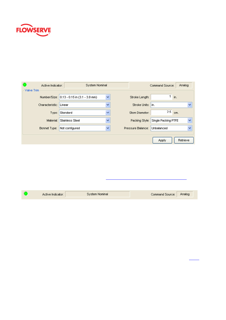
Valve Trim
The Valve Trim page allows you to record information about the connected valve assembly.
NOTE: This information is for record keeping and information purposes only and does not
affect the operation of the positioner or control valve.
Status Area
The Active Indicator area shows the status of the most relevant active indicator. The color
of the "LED light" corresponds to the Active Indicator and the first color of the blink code
sequence on the positioner. Generally green indicates no immediate issues. Yellow
indicates a developing issue. Red indicates the ability to control may be compromised. A
detailed list of the indicators is given in the
Alarm Congfiguraion - Alarm Annunicator
page.
The Command Source field indicates weather the positioner is being controlled by digital or
an analog (4-20 mA) command source.
Valve Trim
The Number/Size field has a drop down menu of trim sizes.
The Characteristic field has a drop down menu of possible trim characteristics. This is
different than the characterization curve that may be applied by the positioner.
The Type field has a drop down menu of trim types.
The Material field has a drop down menu of trim materials.
The Bonnet Type field has a drop down menu of bonnet types.
In the Stroke Length field enter the stroke length of the valve.
NOTE: The correct selection of Stroke Length is important for stroke counting diagnostics.
In the Stroke Units field enter the desired units.
In the Stem Diameter field enter the stem diameter. The units can be changed on the
Units
page of the DTM.
The Packing Style field has a drop down menu of packing styles.
The Pressure Balance field has a drop down menu of trim balance styles.
Action Buttons