1 support structure requirements – Daktronics AF-3700-34 RGB User Manual
Page 9
Mechanical Installation
3
Section 2:
Mechanical Installation
Read the Mechanical, Power, and Signal Installation sections before installing the display(s).
Daktronics engineering staff must approve any changes that may affect the weather-
tightness of the display. If any modifications are made, detailed drawings of the changes
must be submitted to Daktronics for evaluation and approval, or the warranty may be
void.
Daktronics is not responsible for installations or the structural integrity of
support structures done by others. The customer is responsible for ensuring that a
qualified structural engineer approves the structure and any additional hardware.
Reference Drawing:
Shop Drawing for specific display size ......................................................... Listed in Appendix A
2.1 Support Structure Requirements
The installer is responsible for ensuring that the mounting structure and hardware
are capable of supporting the display, and that the structure follows all local codes.
Support structure design depends on the mounting methods, display size, and weight.
Because every installation site is unique, no single procedure is approved by Daktronics for
mounting GalaxyPro
™
displays. The information contained in this section is general
information only and may or may not be appropriate for this particular installation. Refer to
Figure 2 and Figure 3 for basic display set-ups.
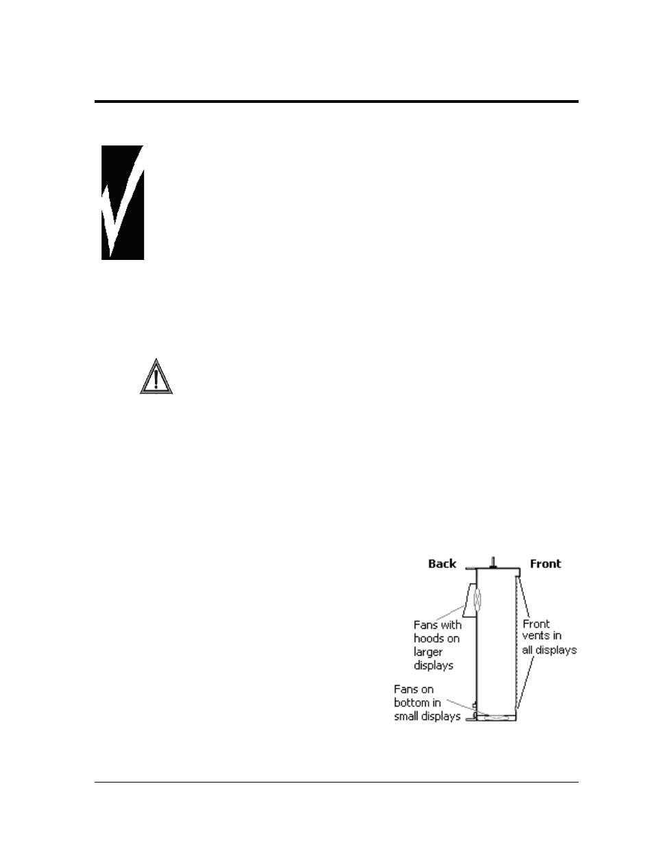
Mounting plans need to take into account the ventilation system for the specific display size.
In general, the front of all displays needs to be unobstructed to allow for air flow and internal
access. Displays 40 pixels high and larger also need unobstructed area in the back to allow for
fans expelling air through the hoods (Figure 4).
Also keep in mind the location of the mounting
clips and the clearance needed for the
power/signal terminations on the back of the
display (Figure 5). Display height and wind
loading are also critical factors to be considered.
This information can be found in the Shop
Drawing which was supplied with the order. These
are also listed in Appendix A.
Figure 4: Ventilation of Displays