1 controller diagnostics – Daktronics AF-3700-34 RGB User Manual
Page 35
Diagnostics and Troubleshooting
29
Section 7:
Diagnostics and Troubleshooting
This section defines the diagnostic LEDs located on the controller, MLC, and temperature sensor.
Troubleshooting tips are also provided for solving display problems.
Safety Precautions
Disconnect power when servicing the display.
Do not modify the display structure or attach any panels or coverings to the display
without written consent of Daktronics.
7.1 Controller
Diagnostics
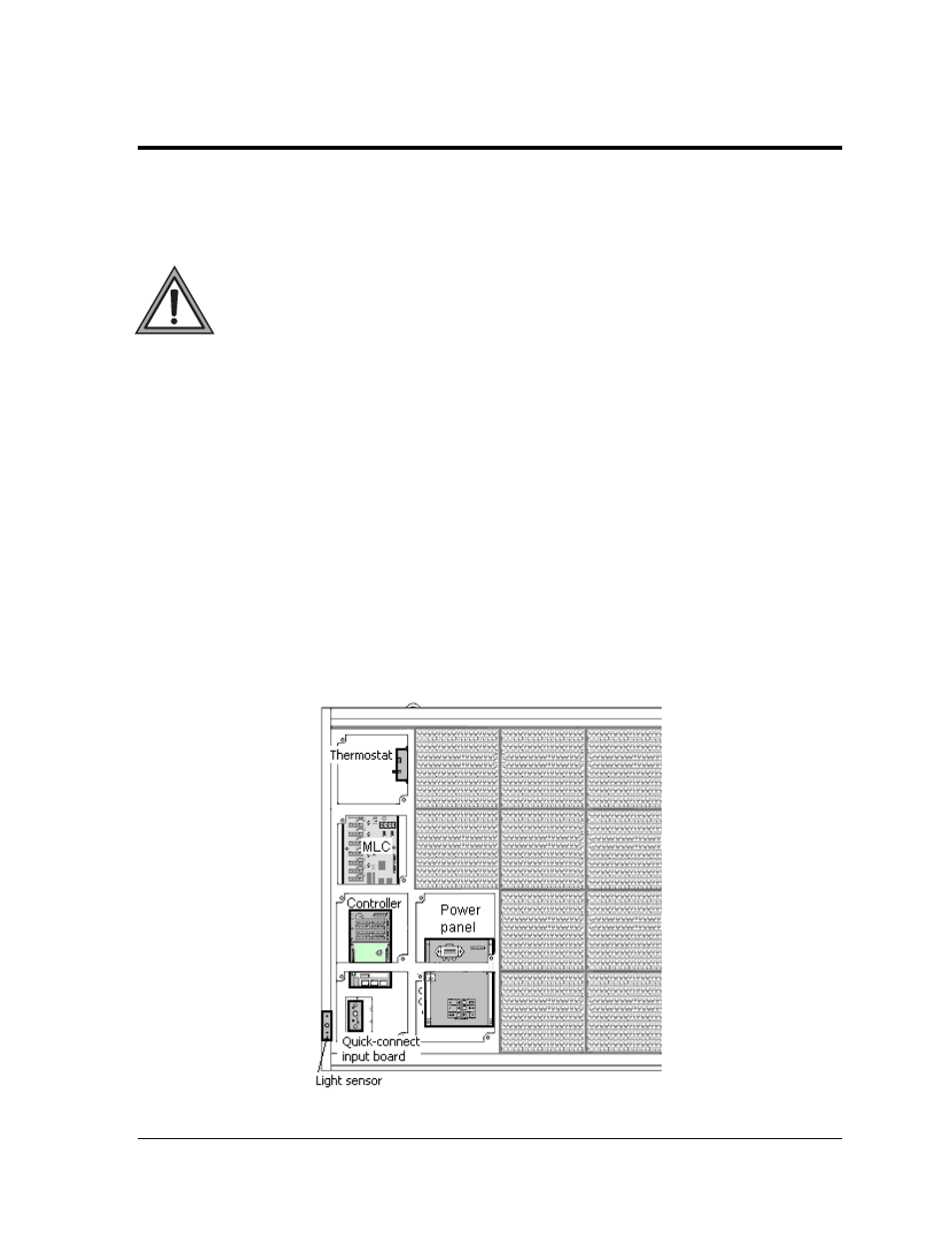
The controller is one of the internal components labeled in Figure 41. This component is the
“brains” of the display, receiving communication from the computer and then sending the
appropriate information to the MLC which outputs to the modules. The LEDs on the
controller are able to show whether the power and communication signal are working
properly.
Since the controller is inside the display, a module or two will need to be removed to view
the diagnostic LEDs. To access the interior of the display, refer to Section 6.1 for instructions
and illustrations.
Remember to disconnect power to the display before accessing the interior.
However, once the modules are removed and wires are found to be safe, power can be
turned back on to view the diagnostic LEDs.
Figure 41: Interior Component Locations