Daktronics AF-3700-34 RGB User Manual
Page 62
Temperature Sensor Mounting For
Galaxy AF-3700 and AF-3500 Displays
page 3 of 5
ED-16704 Rev 2
28 May 2010
201 Daktronics Drive PO Box 5128, Brookings, SD 57006-5128
tel: 866-343-3122 fax: 605-697-4700
www.daktronics.com
1.4 Using more than 25-feet of cable and no quick-connect plug
(rare use)
1. Run ½” conduit from the temperature sensor location to a knockout on the back of the
primary display. The cable must be routed through ½” metal conduit that is earth-
grounded to protect the sensor and controller from lightning damage.
2. Use a 2-pair, 22 AWG,
individually shielded cable to
connect the sensor to the 4-
position terminal block in the
display labeled TB4. Connect to
the controller as shown in
3. Open the temperature sensor
housing by removing the four
nuts from the bottom and
removing the five bottom disks.
Refer to Drawing A-198371 for
details on sensor housing
disassembly.
4. Disconnect the quick-connect
CAN temperature sensor cable
from the temperature sensor terminal block in the CAN temperature sensor housing.
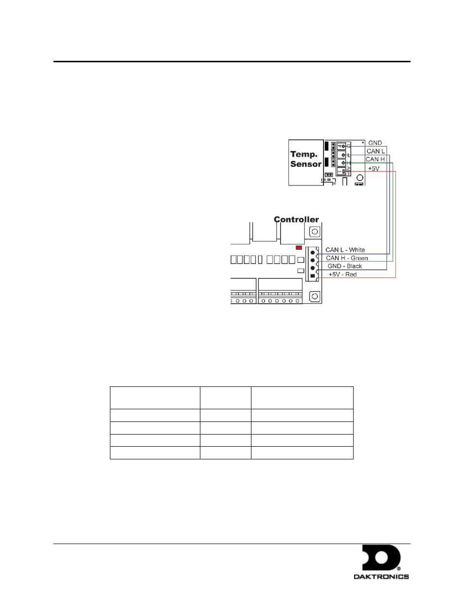
5. Connect the cable coming from the controller’s terminal block to the temperature
sensor board in the temperature sensor housing. Refer to Figure 6 and the following
table for wiring locations and connections at the sensor and to the controller.
6. Route cable around the sensor board as shown in Drawing A-197884.
7. Connect the cable and reassemble the sensor.
Note: The cable length from the sensor to the last display should not exceed 500 feet.
Figure 6: CAN Temperature Sensor Connection Controller
Primary – Controller
Board (A31-TB4)
Field
Cabling
CAN Temp Sensor (TB1)
Pin 1 (+5V CAN)
Red
Pin 1 (+5V CAN)
Pin 2 (GND CAN)
Shield Black
Pin 4 (GND CAN)
Pin 3 (CAN H)
Green
Pin 2 (CAN H)
Pin 4 (CAN L)
White
Pin 3 (CAN L)