Daktronics AF-3700-34 RGB User Manual
Page 48
Parts Replacement
42
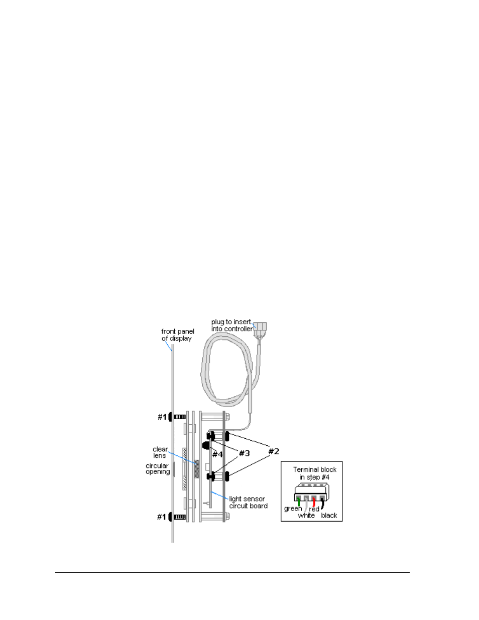
Light Sensor Replacement
The light sensor assembly is mounted inside the bottom left edge of the cabinet. Refer to
Figure 41 for location. The entire assembly fits over two screws.
If the light sensor should fail, only the circuit board needs to be replaced. Remove the bottom
left module on the display to access the light sensor. To replace a light sensor circuit board
(Figure 55), follow these steps.
Note: The hardware mentioned in each step is given a corresponding number in the drawing.
For instance, the nuts mentioned in step 2 are labeled #2 in the figure.
Tool required: #4 hex driver, Phillips screwdriver
1. Remove the screws that hold the light sensor to the cabinet.
2. Remove the #4-40 nuts securing the circuit board to the plate.
3. Remove the standoffs and attachment screws from the board.
4. Disconnect the four electrical wires on the sensor by unscrewing each screw that
holds a wire in place. Note the order that the wires are connected so that they can be
reconnected in the same locations on the replacement.
5. The light sensor plug on the controller does not need to be detached.
6. Reattach the new circuit board, following these steps in reverse.
Note: Align the new circuit board so that the lens lines up with the 1/2" circular opening in
the bottom left edge of the display when the assembly is in place.
Figure 55: Light Sensor Assembly