Daktronics AF-3700-34 RGB User Manual
Page 19
Power Installation
13
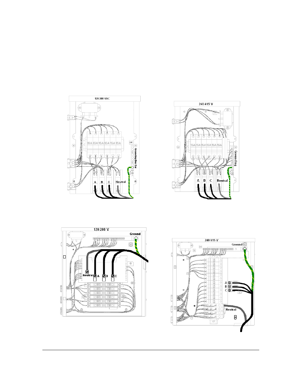
Terminating 3-phase power to the internal power termination panel:
1. Open the display as explained in Section 6.1 and locate the power termination panel.
2. Route the cable through conduit to the back of the display. Use one of the knockouts
for access, being careful not to damage internal components.
3. Connect the neutral wire to the neutral lug and the live wires to the lugs labeled A, B,
and C. Refer to Figure 16 and Figure 17 for 6-breaker panels for 120/208 and 240/415
voltages. Figure 18 and Figure 19 show the 12-breaker power termination panels.
4. The ground wire connects to the grounding bus bar.
Figure 16: 240/415 VAC Power
Termination – 6-breaker
Figure 17: 120/208 VAC Power
Termination – 6-breaker
Figure 18: 120/208 V Power Termination –
12 breaker
Figure 19: 240/415 V Power Termination –
12 breaker
- TI-3031 4-Inch LED Bar-Digit Locker Room Clock (22 pages)
- ST-2005 Backlit & Non-Backlit Scorer’s Tables (24 pages)
- BB-2135 Backboard LED Light Strip (36 pages)
- TN-2563 Tuff Sport Indoor Multi-Court Tennis LED Scoreboard (112 pages)
- BB-2144 Tuff Sport Basketball LED Scoreboard (184 pages)
- TN-2607 Single-Court Outdoor LED Tennis Scoreboard (134 pages)
- CR-2004 Multi-Section Cricket Scoreboard (90 pages)
- FT-7150 Touchpad (29 pages)
- SW-2008 Aquatics/Track LED Scoreboard (84 pages)
- SO-1424-11 Multi-Section Outdoor LED Scoreboard (158 pages)
- FB-4005-31 DistaView Outdoor LED Scoreboard (64 pages)
- MS-2018 Generation III Stackable LED Scoreboard (76 pages)
- GM-2103 LED Gymnastics Scoreboards (38 pages)
- HS-200 Horn Start (36 pages)
- Indoor Hockey Goal Lights (44 pages)
- LED End-of-Period Basketball Lighting (34 pages)
- MS-2013 Portable LED Scoreboard (52 pages)
- WR-2106 Matside Jr. LED Wrestling Scoreboard (44 pages)
- TI-2021 Multipurpose Track & Field LED Timing Display (50 pages)
- P1647 Multi-Section Outdoor LED Scoreboard (52 pages)
- P1647 Multi-Section Outdoor LED Scoreboard (50 pages)
- DA-1200 Outdoor Decorative Accent (30 pages)
- 2000 Rodeo OmniSport (72 pages)
- Outdoor LED Scoreboards Installation (58 pages)
- Outdoor LED Scoreboards Service Manual (52 pages)
- SO-2014 Generation IV Multi-Section Outdoor LED Scoreboard (208 pages)
- P1647 Multi-Section Outdoor LED Scoreboard (44 pages)
- PC-2001 Pace Clock System (40 pages)
- PC-2002 Pace Clock System (32 pages)
- BB-314 Portable LED Basketball Scoreboard (28 pages)
- Protective Screen (4 pages)
- TI-2002 Portable LED Timer (32 pages)
- Radar Gun Speed of Pitch Interface (27 pages)
- TI-2026 Segment Timer (28 pages)
- Single-Section Outdoor LED Scoreboards (46 pages)
- LED Aquatics/Track Displays SW-2000 Series 10 Numeric Digit (86 pages)
- TI-2022 Portable LED Timer (32 pages)
- Single Section DistaView Outdoor LED Scoreboards Generation IV (99 pages)
- BB-2151 (NBA only) Transparent Shot Clock (48 pages)
- TN-2563 Tuff Sport Indoor LED Tennis Scoreboard (34 pages)
- Scoreboard Trumpet Horn (50 pages)
- ST-3001 Tuff Sport & ColorSmart LED Scorer’s Table (48 pages)
- Tuff Sport & ColorSmart Indoor LED Scoreboards (46 pages)
- Tuff Sport Indoor LED Scoreboards (40 pages)
- Tuff Sport& ColorSmart FourSided Indoor LED Scoreboards (58 pages)