Daktronics AF-3700-34 RGB User Manual
Page 25
Signal Installation
19
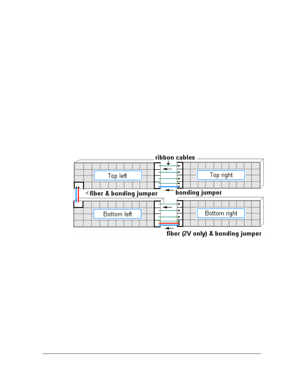
Four (4) Section Interconnections
• Locate the fiber cable in the bottom left corner of the top left section. Insert it through
the hub into the bottom section and connect to the fiber coupler located in the top left
module opening.
• Locate the bonding jumper in the bottom left end of the top left section. Route
through holes between display sections into the top left end of the bottom left section
and connect to the bonding jumper stud.
• Locate the bonding jumper in the bottom left end of the top right section. Route
through holes between display sections into the right end of the top left section and
connect to the bonding jumper stud.
• Locate the bonding jumper in the lower left end of the bottom right section. Route
through the holes between display sections and connect to the bonding jumper stud.
• Connect ribbon cables along the seam between displays from the right sections to the
left sections.
• When a Mirror display is being used (2V configuration), locate the fiber cable in the
bottom left end of the bottom right section and route through the holes between
display sections and connect to the fiber coupler in the right end of the bottom left
section.
Figure 30: Interconnections between Four Sections