2 signal and bonding interconnections – Daktronics AF-3700-34 RGB User Manual
Page 24
Signal Installation
18
4.2 Signal and Bonding Interconnections
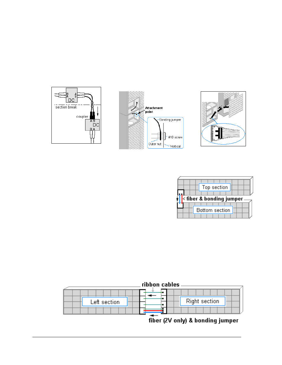
Three types of cables run between sections to connect signal and ground. Signal runs
between display sections by connecting fiber cables to installed couplers (Figure 25). Bonding
jumpers are used to connect all display sections together, requiring that only one section be
connected to the ground rod (Figure 27). Ribbon cables are used to connect signal between
modules (Figure 26). Refer to the following instructions on connecting these between
sections. Refer to Fiber Routing Drawings located in Appendix A for additional detail.
Between Top and Bottom Sections
• Locate the fiber cable in the bottom left corner of
the top section. Insert it through the hub into the
bottom section and connect to the fiber coupler
located in the top left module opening.
• Locate the bonding jumper in the bottom left
corner of top section. Insert it through the hub into
the bottom section and connect to the bonding
jumper stud in the top left end of bottom section.
Between Left and Right Sections
• Locate the bonding jumper in the lower left end of the right section. Route through
into the left section and connect to the bonding jumper stud.
• Connect ribbon cables along the seam between displays from the right section to the
left section.
• When a Mirror display is being used (2V configuration), locate the fiber cable in the
bottom left end of the right section. Route through the holes between display sections
and connect to the coupler in the right end of the left section.
Figure 25: Fiber
Interconnections
Figure 26: Ribbon Cable
Figure 27: Bonding Jumper Detail
Figure 28: Top/Bottom Interconnections
Figure 29: Right/Left Interconnections