Daktronics AF-3700-34 RGB User Manual
Page 11
Mechanical Installation
5
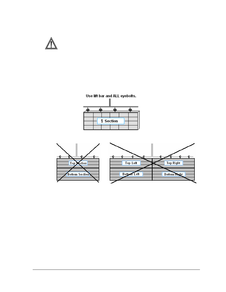
2.2 Lifting a Display or Display Section
In order to maintain the structural integrity of the display cabinet, the 90
° angle
between the cabinet and the lifting method must be maintained.
If damage occurs due to improper lifting procedures, the warranty will be void.
General Lifting Notes:
• Lift the display into position on the support structure using a lifting bar and all
eyebolts. (Figure 6).
• Do not attempt to permanently support the display by the eyebolts.
• Do not lift more than one section at a time with the eyebolts.
• Mount bottom section(s) first.
Left and right sections may be mounted together ONLY if a lifting bar and all eyebolts
are used. Left/right signal and ground connections may be easier to make on the ground.
Top/bottom or more than two sections should not be mounted together since the
eyebolts and connecting hardware are not strong enough for this procedure.
After installation is complete, carefully inspect the display for any holes that may allow
water to seep into the display and seal any openings with silicone.
If the eyebolts on the top of the display have been removed, plug the holes with bolts
and the rubber-sealing washer that was removed with the eyebolt unless an overhead
structure protects the area.
Refer to Section 3 for power routing and to the appropriate communication manual for
signal connections to the display.
Figure 6: Correct Lifting Procedure
Figure 7: Incorrect Lifting