4 wire ethernet communication – Daktronics AF-3700-34 RGB User Manual
Page 27
Signal Installation
21
4.4 Wire Ethernet Communication
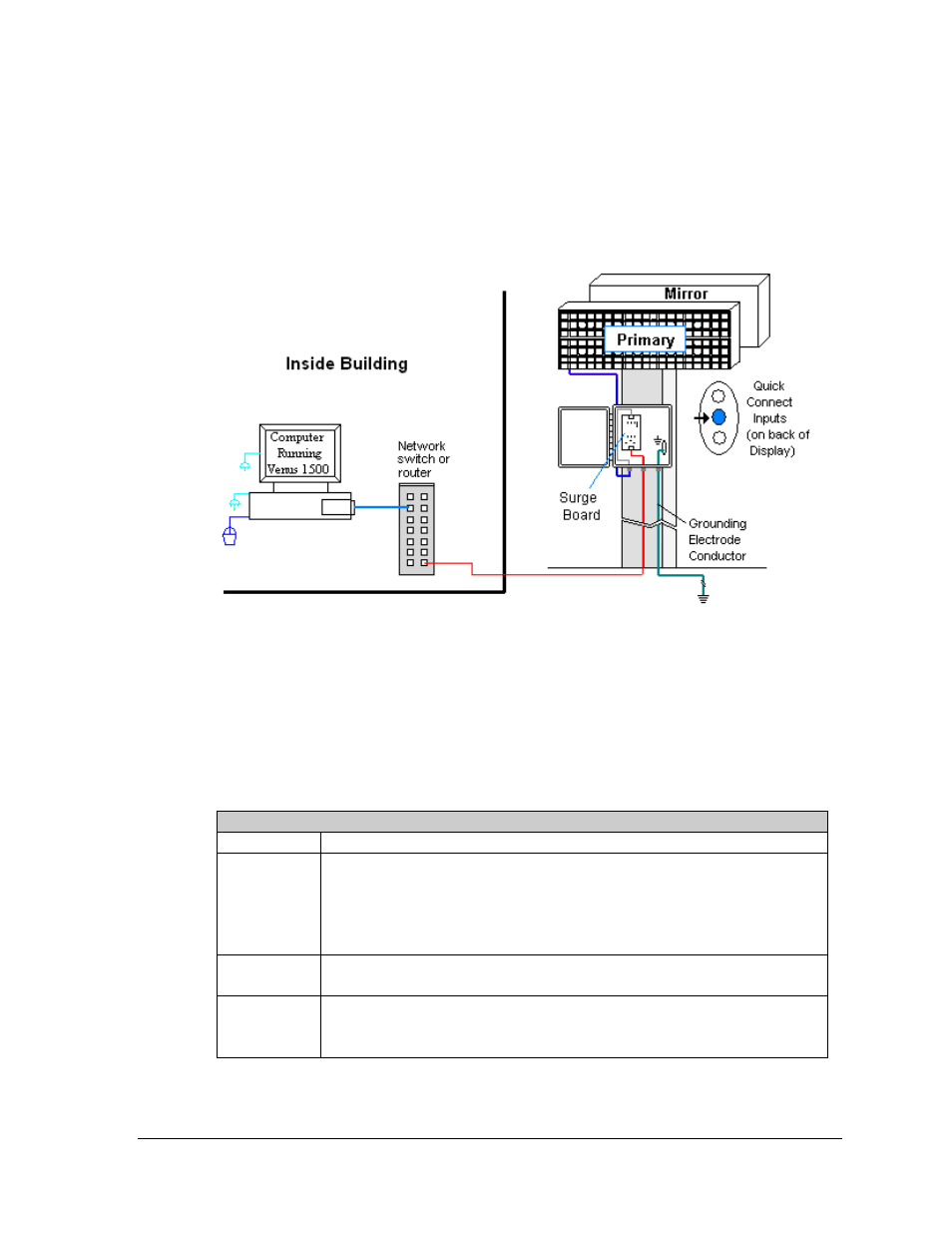
If the communication system is Wire Ethernet, look for:
• a network card in the computer connecting to a network switch.
• a network jack that looks similar to an oversized phone jack.
Connections
• Computer to network − RJ45 cable from computer port to network server in building.
• Network switch to surge board − another RJ45 cable from switch to surge board in
enclosure at display.
• Enclosure at the display to display − quick-connect cable from the enclosure to
middle jack on back of display.
Troubleshooting
Component Check:
Cable
Connections
•
An RJ45 cable connects the computer to the network
switch
or router.
•
An RJ45 cable from the server is connected to the input port on the
Ethernet surge board at the display.
•
The quick-connect cable runs from the enclosure to the middle jack on
display back.
Display
Power
•
The display is either running a message or showing a single pixel flashing
in the bottom right corner of the display when power is on.
Software
• The software is configured for TCP/IP communication.
• The software and the display are set to the same network address.
• Refer to the software manual for other possible conditions.
Figure 32: Ethernet Communication Layout