4 optional temperature sensor mounting – Daktronics AF-3700-34 RGB User Manual
Page 14
Mechanical Installation
8
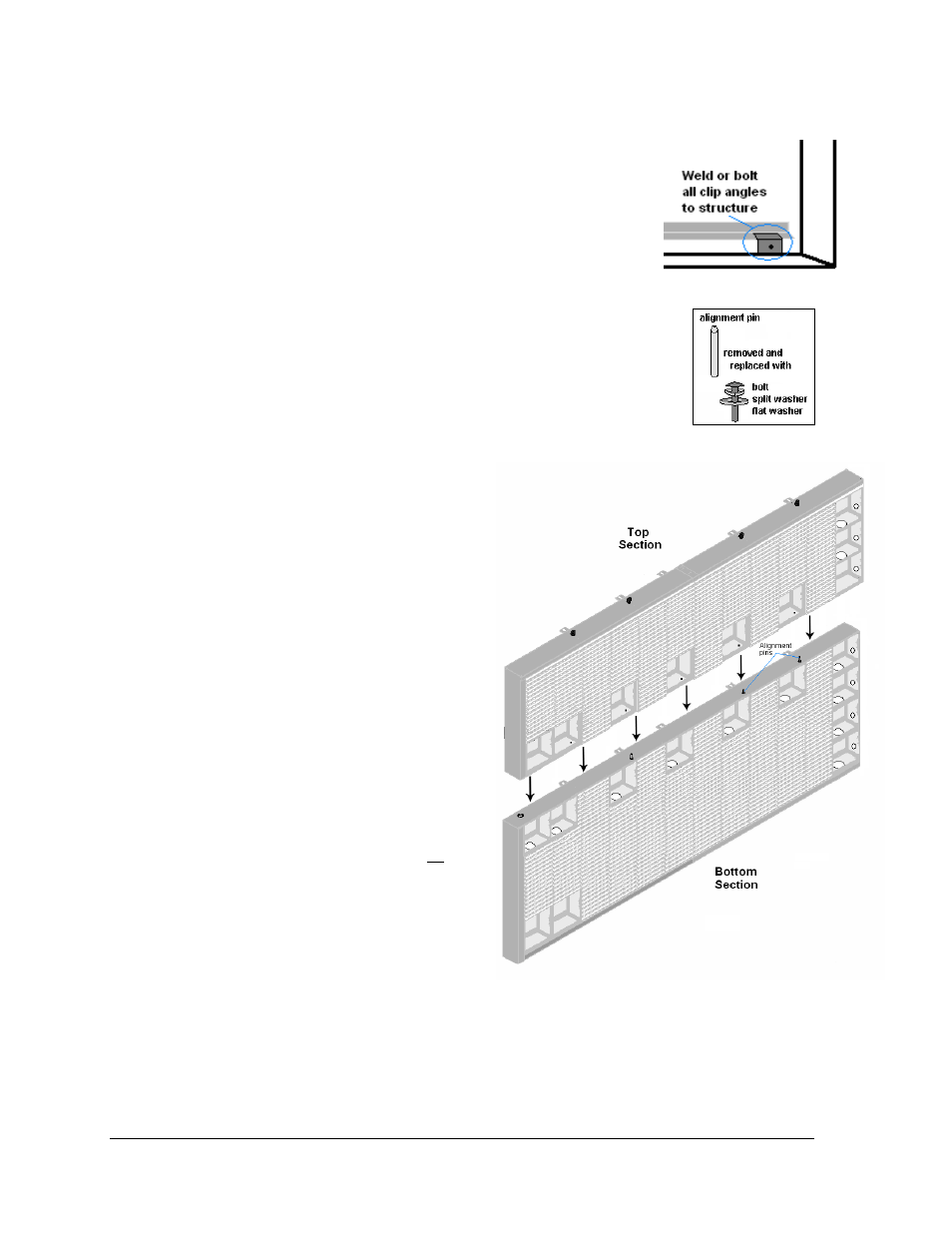
Combining Sections
1. Install the alignment pins in the top edge of the bottom
section by screwing them into the holes where the eyebolts
were located.
2. Attach the bottom section to the support structure by welding
or using 1/2” grade-5 bolts and hardware. Secure all clip
angles. Refer to Figure 10.
3. Set the top section on top of the bottom section with the aid of the
alignment pins.
4. Attach the top to bottom sections by unscrewing the alignment
pins and replacing them with the following (Refer to Figure 11):
• ½”-13 X 1 ½” bolts (HC-1152)
• ½” split washers (HC-1101)
• ½” flat washers (HC-1095).
Fill in all holes in the adjoining
sections.
5. If additional sections will be added
for length, remove the covers from
interconnection openings. Attach the
left to right sections with the
following:
• ½”-13 X 1 ½” bolts (HC-1152)
• ½” split washers (HC-1101)
• ½” flat washers (HC-1095).
Fill in all holes in the adjoining
sections.
6. Attach the top section(s) to the
structure. Weld or use ½" grade-5
bolts and hardware to secure all clip
angles to the support structure.
2.4 Optional Temperature Sensor
Mounting
If an optional temperature sensor will be used with this display, refer to Appendix C for
mounting and signal connections.
Figure 10: Clip Angle Detail
Figure 11: Alignment Pin
Figure 12: Attaching Top and Bottom Sections