Daktronics AF-3700-34 RGB User Manual
Page 46
Parts Replacement
40
MLC Replacement
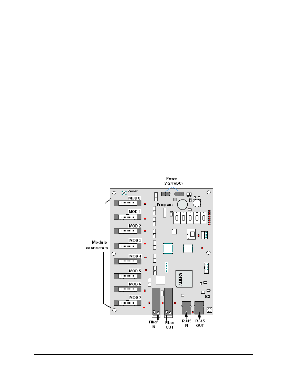
The Multi-Line Controller (MLC) receives signal via fiber cable from the controller or another
MLC and distributes it to the modules (Figure 52). One MLC will be present in displays up to
64 pixels high and two MLCs are installed in larger displays. Ribbon cables run from the
module connectors on the MLC to the first modules in each row via ribbon cables. The power
supply nearest the MLC will provide its power.
Tools required: Nutdriver
1. Turn off power to the display.
2. Remove the module directly in front of the MLC. Typically, this is in the left end of
the display section, approximately the third module from the bottom of the cabinet.
Refer to the appropriate Layout Drawing for exact location.
3. Disconnect the fiber cables.
4. Remove all ribbon cables, labeling the module number as they are removed to insure
proper replacement.
5. Remove the six nuts holding the board in place using a 5/16" nut driver.
6. To install the new MLC, move the unit into place and replace the six nuts holding it
to the display back. Reconnect fiber and ribbon cables. Turn on power, observing the
boot-up sequence. Note that the LEDs to the right of the fiber cables are on; DS23 to
the left of the fiber cable should be off. Refer to Figure 43.
Figure 52: MLC