3 wireless ethernet bridge communication – Daktronics AF-3700-34 RGB User Manual
Page 26
Signal Installation
20
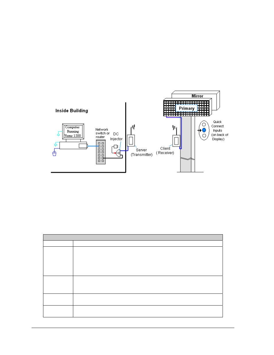
4.3 Wireless Ethernet Bridge Communication
If the communication system is a Wireless Ethernet Bridge, look for:
• a network card in the computer connecting to a network switch or router.
• a server radio mounted on the building and a client radio at the display.
Note: This system is referred to as a “bridge” because the radios are configured as a matched
pair. Therefore, if one radio needs to be replaced, both will have to be replaced.
Connections
• Computer to network − RJ45 cable from computer port to network server in building.
• Network switch to DC injector
• Wall power adapter from 120 VAC outlet to DC injector.
• Network cable from DC injector to server radio.
• Clear line of sight between server radio and client radio.
• Client radio to display − quick-connect cable to the middle jack on display back.
Figure 31: Wireless Ethernet Bridge Layout
Troubleshooting
Component Check:
Cable
Connections
•
A cable connects the computer to the network switch or router.
•
A cable runs from the network switch to the DC injector.
•
A cable runs from DC injector to server radio.
•
The quick-connect cable is connected from the client radio to the middle jack
on back of display.
Diagnostic
LEDs
•
The green LEDs will be on when DC injector has power.
•
The server and client radios have internal LEDs. Refer to the Wireless
Ethernet manual for their specifications.
Display
Power
•
The display is either running a message or showing a single pixel flashing in
the bottom right corner of the display when power is on.
Software
•
The software and the display are set to the same network address.
•
Refer to the software manual for other possible conditions.