3 temperature sensor diagnostic, 4 troubleshooting display problems – Daktronics AF-3700-34 RGB User Manual
Page 37
Diagnostics and Troubleshooting
31
7.3 Temperature Sensor Diagnostic
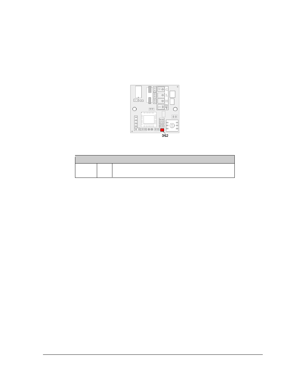
If the display includes a temperature function, the temperature sensor board will also
provide diagnostic information. The temperature sensor board is located inside the
temperature sensor housing which hangs near the display (Figure 44). The sensor board
diagram below shows the red diagnostic LED (DS2) near the bottom edge of the component.
Refer to Appendix C for temperature sensor mounting and connections.
7.4 Troubleshooting Display Problems
This section contains some symptoms that may be encountered in the displays. This list does
not include every possible symptom or solution but does represent common situations and
simple steps to resolve them. The solutions are given in priority order so try the first solution
first.
Troubleshooting may require removal and replacement of modules. Refer to Section 6.1 for
instructions on this procedure. When replacing modules, make sure that the power and
signal cables are reconnected correctly and the latches are tightly closed.
Module and LED problems
One or more LEDs are not lighting
• Check/replace the ribbon cables on the module.
• If that does not help, the module may need to be replaced.
One or more LEDs on a single module will not turn off
• Check/replace the ribbon cables on the module.
• If that does not help, the module may need to be replaced.
Figure 44: Temperature sensor board
Temperature Sensor
DS2
Run
FLASH at variable rates when sending temperature
information; evidence that the unit has power.