6 sensor replacement – Daktronics AF-3700-34 RGB User Manual
Page 63
Temperature Sensor Mounting For
Galaxy AF-3700 and AF-3500 Displays
page 4 of 5
ED-16704 Rev 2
28 May 2010
201 Daktronics Drive PO Box 5128, Brookings, SD 57006-5128
tel: 866-343-3122 fax: 605-697-4700
www.daktronics.com
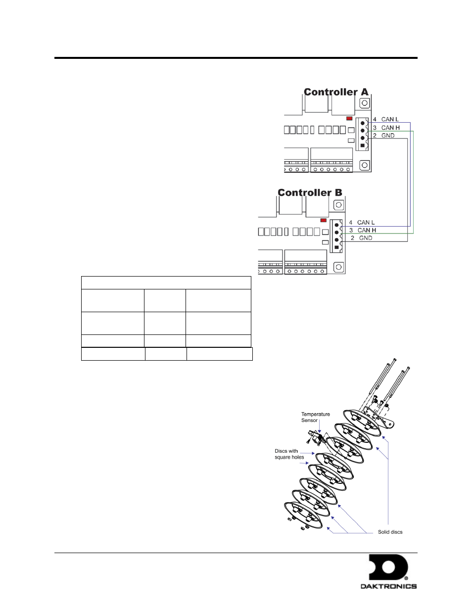
1.5 Temperature Interconnection
(for primary-primary setups)
When the display uses the quick-connect
interconnect cable, this connection is already
complete.
When the interconnect cable is not used, a 4-
conductor shielded cable is needed to terminate
the temperature sensor from display one to
display two.
One end terminates at the 4-position terminal
block (TB4) on the primary display. The other
end terminates at the 4-position terminal block
(TB4) in the second display. Refer to Figure 7
and the following table for correct interconnect
locations.
Note: Do not connect the wire to pin one on
either display.
Interconnect Locations – M3 Controller
Primary
(A31-TB4)
Field
Cabling
Secondary
(A31-TB4)
Pin 2 (GND
CAN)
Black
Pin 2 (GND CAN)
Pin 3 (CAN H)
Green
Pin 3 (CAN H)
Pin 4 (CAN L)
White
Pin 4 (CAN L)
1.6 Sensor Replacement
If the temperature sensor board or wiring
malfunctions, access it by:
1. Open the temperature sensor housing by
removing the four nuts from the bottom and
then removing the five bottom disks. Refer to
Figure 8 for details on sensor housing
disassembly.
2. Label the wires connected to the temperature
sensor board and then disconnect the cable
from the sensor terminal block in the
temperature sensor housing.
Figure 7: CAN Controller Interconnect
Figure 8: Temperature Sensor Diagram