1 primary/mirror signal connection – Daktronics AF-3700-34 RGB User Manual
Page 23
Signal Installation
17
Section 4:
Signal Installation Overview
Daktronics GalaxyPro
™
displays are equipped to receive various Ethernet communication signals.
The following sections include a brief description of each available type. Also included is a list of
troubleshooting tips to check that the display is connected and configured correctly.
For specific details on installing the communication signal, consult the quick guide and manual
included in the box with the communication equipment. Each type of communication is listed below
with its manual number.
Note: These are the standard communication types, but each site is unique and may include
additional equipment. If problems arise, contact the display’s seller, service company, or Daktronics
Customer Service.
Reference Drawings:
Routing, Fiber, MM, LC, AF-3700-(8-64x48-304)-34 .......................................... Drawing B-287914
Routing, Fiber, MM, LC, AF-3700-(8-64x320-384)-34 ........................................ Drawing B-287915
Routing, Fiber, MM, LC, AF-3700-(72-128x48-304)-34 ...................................... Drawing B-287916
Routing, Fiber, MM, LC, AF-3700-(72-128x320-384)-34 .................................... Drawing B-287917
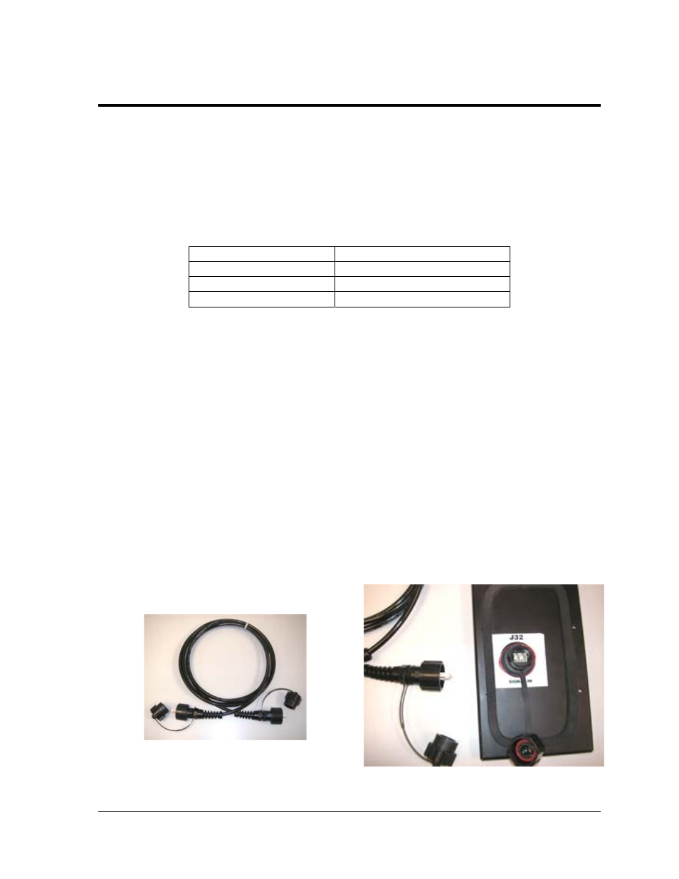
4.1 Primary/Mirror Signal Connection
If this display is a two-sided primary/mirror display, a quick-connect fiber cable will be
provided to connect the signal between the two display faces. Connect J34-Signal Out on the
Primary display to J32-Signal In on the Mirror display. Secure the excess cable to the supports
to prevent damage from weather or vandalism. Refer to Figure 24 and Figure 23 for an
illustration of the cable and the quick-connect input.
Communication Type
Communication Manual ED#
Wireless Ethernet Bridge
ED-16483
Ethernet
ED-14745
Fiber Ethernet
ED-14746
Figure 23: Fiber Interconnect Cable and Input
Figure 24: Quick-Connect Signal Cable