2 utility connectors – Comtech EF Data LBC-4000 User Manual
Page 41
LBC-4000 L-Band Up/Down Converter System
Revision 4
Rear Panel Connections
MN/LBC4000.IOM
3–7
3.2.2
Utility Connectors
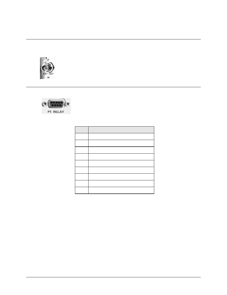
3.2.2.1 J2 | EXT REF (External Reference) Input Connector (Type ‘BNC’
Female)
The J2 | EXT REF IN (External Reference Input) is used to supply a master reference
to the entire chassis. The input signal supplied here by the user is used for phase‐
locking the internal 10MHz reference oscillator to a customer‐provided 5 or 10 MHz
station clock. The impedance is matched for 50/75Ω, and requires a level in the
range 0.5V‐4.0Vpp square or sine wave.
3.2.2.2 P1 | RELAY (Summary Fault Output) Connector (DB-9F)
The P1 | RELAY summary fault output is a 9‐pin Type "D" female (DB‐9F)
connector.
Table 3-2. P1 | RELAY Connector Pinouts
Pin #
Description
1 SUMFLT1_NC
6
SUMFLT1_COM
2 SUMFLT1_NO
7
NC
3 SUMFLT2_NC
8
SUMFLT2_COM
4 SUMFLT2_NO
9
NC
5 GND
Notes – For Normal Fault Relay Logic:
1. Pin 1 to Pin 6: OK – No Fault
2.
Pin 2 to Pin 6: Fault
- CDD-880 (124 pages)
- CDM-800 (130 pages)
- ODMR-840 (184 pages)
- CDM-750 (302 pages)
- CDM-840 (244 pages)
- SLM-5650A (420 pages)
- CTOG-250 (236 pages)
- CDM-700 (256 pages)
- CDM-760 (416 pages)
- CDM-710G (246 pages)
- CDM-600/600L (278 pages)
- CDMR-570L (512 pages)
- CDM-625 (684 pages)
- CDM-625A (756 pages)
- CDD-564A (240 pages)
- CDD-564L (254 pages)
- CLO-10 (134 pages)
- MCED-100 (96 pages)
- CDMR-570AL (618 pages)
- CDM-600 LDPC (2 pages)
- BUC Power Supply Ground Cable (2 pages)
- MPP70 Hardware Kit for CDM-570L (4 pages)
- MPP50 Hardware Kit for CDM-570L (4 pages)
- CDM-625 DC-AC Conversion (4 pages)
- CDM-625 DC-AC Conversion with IP Packet Processor (4 pages)
- DMDVR20 LBST Rev 1.1 (117 pages)
- DMD2050E (212 pages)
- DMD-2050 (342 pages)
- DMD1050 (188 pages)
- OM20 (220 pages)
- QAM256 (87 pages)
- DD240XR Rev Е (121 pages)
- MM200 ASI Field (5 pages)
- DM240-DVB (196 pages)
- MM200 (192 pages)
- CRS-150 (78 pages)
- CRS-280L (64 pages)
- CRS-170A (172 pages)
- CRS-180 (136 pages)
- SMS-301 (124 pages)
- CiM-25/8000 (186 pages)
- CiM-25 (26 pages)
- CRS-500 (218 pages)
- CRS-311 (196 pages)
- CIC-20 LVDS to HSSI (26 pages)