C.3 dual-base (chain) redundancy operation – Comtech EF Data MBT-4000 User Manual
Page 74
MBT-4000 Multi-Band Transceiver System
Revision 4
Redundancy Configuration / Operation
MN/MBT4000.IOM
C–2
1:1 MBT SUBSYSTEM
BDC 2 (Slot 2)
BUC 2 (Slot 1)
SSPA 2
1:1 MBT SUBSYSTEM
BDC 1 (Slot 2)
BUC 1 (Slot 1)
LNA 1
LOAD
L
-B
A
ND O
U
T
LOAD
L-
BAN
D
IN
SSPA 1
J3
J3
J6
J6
J10
J10
LOAD
TX
REJECT
FILTER
RX
REJECT
FILTER
J7
J7
J8
J8
J9
J9
AUX COMM 1
AUX COMM 2
AUX COMM 2
SWITCH 2 RF
SWITCH 1 RF
SWITCH 2 IF
REDUNDANCY
INTERLINK CABLE
AUX COMM 1
SWITCH 1 IF
L-BAND
MODEM
TX
RX
WAVEGUIDE
WAVEGUIDE
LNA 2
MBT
A
M
BT
B
J5
J5
UNIT 1
COMM
UNIT 1
COMM
UNIT 2
COMM
UNIT 2
COMM
RF SWITCHES
SHOWN IN
POSITION
B
C.3
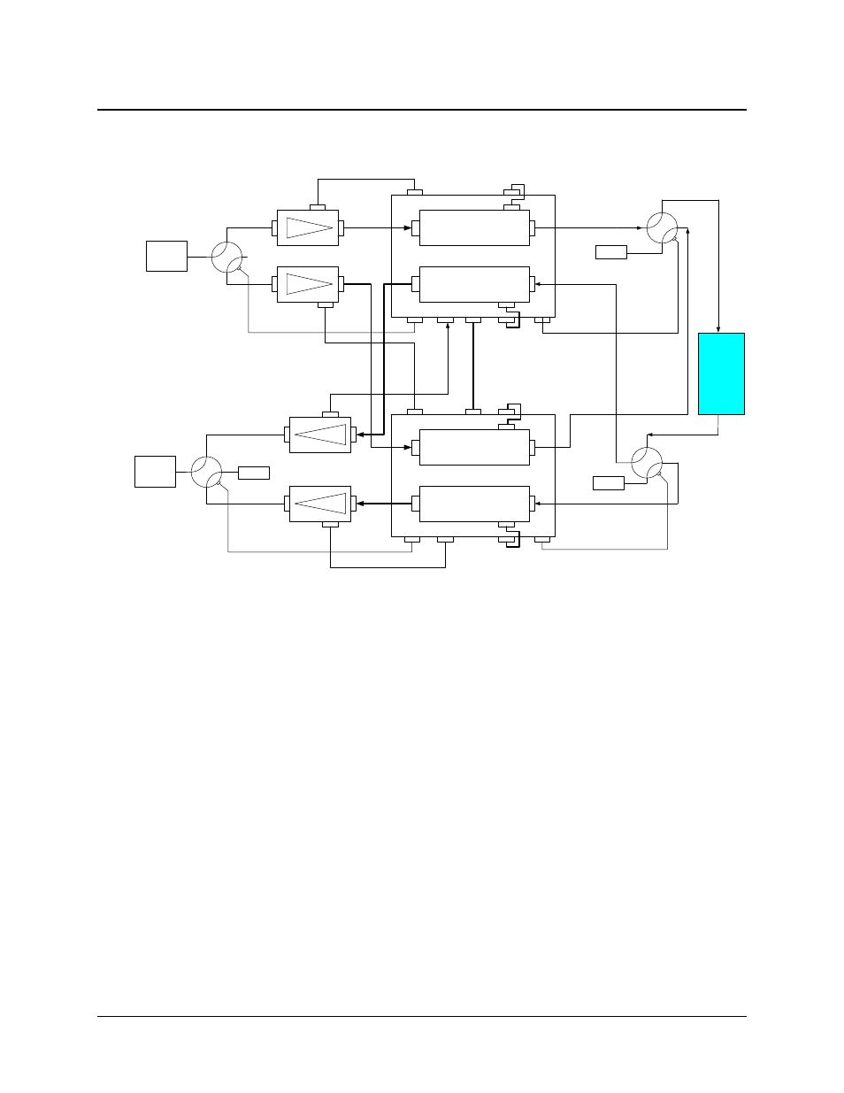
Dual-Base (Chain) Redundancy Operation
Figure C-1. Dual-Base (Chain) Redundancy Operation
Figure C-1 illustrates a typical Dual-Base (Chain) Redundancy configuration. The two
MBT-4000 base units cooperate in monitoring the health of the four BxCs (and each other). In
case of a fault on an online BxC the MBT-4000 base containing the corresponding standby BxC,
will automatically switch over to the standby BxC in accordance with the following rules:
1. In dual-base (chain) redundancy operation, the redundancy is ‘slot’ based. The
corresponding pairs reside in the same ‘slot’ of the opposite MBT-4000 base, the pair of
BxCs connected to J3 UNIT 1 COMM (Slot 1) on each base form a redundant pair. The
BxCs connected to J6 UNIT 2 COMM (Slot 2) on each base form the other redundant
pair. Typically, one pair is used for up conversion and the other for down.
2. The corresponding BxCs in a pair must be of the same type.
3. The Redundancy Interlink Cable (CEFD P/N CA/WR11224-1 or equivalent) must be
installed.
4. Base unit identification(MBT-A or MBT-B) is driven by the redundancy interlink cable.
Hard wired connections within the cable designate one MBT-4000 base as MBT-A and
the other as MBT-B. The cable is labeled accordingly.
5. The RF and IF switches connected to MBT-A correspond to the redundant pair of BxCs
installed on J3 UNIT 1 COMM (Slot 1).