4 rf switch (j10), Rf out (j5, buc-4000 only), 6 rf in (j5, bdc-4000 only) – Comtech EF Data MBT-4000 User Manual
Page 36
MBT-4000 Multi-Band Transceiver System
Revision 4
External Connectors
MN/MBT4000.IOM
3–10
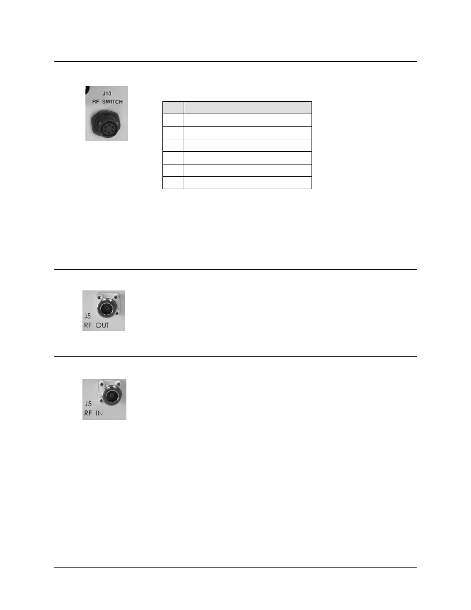
3.2.2.4 RF SWITCH (J10)
Table 3-11. RF Switch (J10) Connector Pinouts
Pin Signal
A
POS 1 RF
B GND
C
POS 2 RF
D
POS 1 IND RF
E GND
F
POS 2 IND RF
NOTE – Mating Connectors:
CEFD P/N CN/MS3116J10-6P
(Cannon MS3116J10-6P)
3.2.2.5 RF OUT (J5, BUC-4000 ONLY)
The J5 RF OUT connector, located on the BUC-4000 Block Up Converter Module,
is a Type ‘N’ female connector, used to provide the upconverted RF Output.
3.2.2.6 RF IN (J5, BDC-4000 ONLY)
The J5 RF IN connector, located on the BDC-4000 Block Down Converter Module,
is a Type ‘N’ female connector, used to provide RF Input for the downcoverter.
See also other documents in the category Comtech EF Data Equipment:
- CDD-880 (124 pages)
- CDM-800 (130 pages)
- ODMR-840 (184 pages)
- CDM-750 (302 pages)
- CDM-840 (244 pages)
- SLM-5650A (420 pages)
- CTOG-250 (236 pages)
- CDM-700 (256 pages)
- CDM-760 (416 pages)
- CDM-710G (246 pages)
- CDM-600/600L (278 pages)
- CDMR-570L (512 pages)
- CDM-625 (684 pages)
- CDM-625A (756 pages)
- CDD-564A (240 pages)
- CDD-564L (254 pages)
- CLO-10 (134 pages)
- MCED-100 (96 pages)
- CDMR-570AL (618 pages)
- CDM-600 LDPC (2 pages)
- BUC Power Supply Ground Cable (2 pages)
- MPP70 Hardware Kit for CDM-570L (4 pages)
- MPP50 Hardware Kit for CDM-570L (4 pages)
- CDM-625 DC-AC Conversion (4 pages)
- CDM-625 DC-AC Conversion with IP Packet Processor (4 pages)
- DMDVR20 LBST Rev 1.1 (117 pages)
- DMD2050E (212 pages)
- DMD-2050 (342 pages)
- DMD1050 (188 pages)
- OM20 (220 pages)
- QAM256 (87 pages)
- DD240XR Rev Е (121 pages)
- MM200 ASI Field (5 pages)
- DM240-DVB (196 pages)
- MM200 (192 pages)
- CRS-150 (78 pages)
- CRS-280L (64 pages)
- CRS-170A (172 pages)
- CRS-180 (136 pages)
- SMS-301 (124 pages)
- CiM-25/8000 (186 pages)
- CiM-25 (26 pages)
- CRS-500 (218 pages)
- CRS-311 (196 pages)
- CIC-20 LVDS to HSSI (26 pages)