2 installation, 3 operation – Comtech EF Data MBT-4000 User Manual
Page 26
MBT-4000 Multi-Band Transceiver System
Revision 4
Installation
MN/MBT4000.IOM
2–2
2.2
Installation
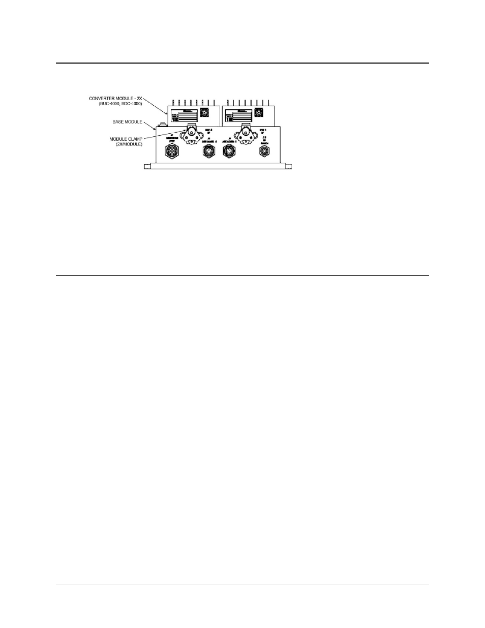
The Base Module for the MBT-4000
system – which provides the M&C,
Power Supply, and Reference
interfaces – may be located near or
on the antenna. Guide pins and
mechanical clamps keep the band-
specific BUC and BDC modules in
place on top of the Base Module.
Cables to the antenna and IDU complete the installation. For complete information on the
MBT-4000’s connectors, including the pinout tables, refer to Chapter 3. EXTERNAL
CONNECTORS.
To change the band of operation, the cables to the BUC/BDC modules are disconnected and the
modules are unlatched from the Base unit, allowing removal and replacement of the existing
modules with appropriate band-specific modules.
2.3
Operation
Once all pertinent connections have been made between the MBT-4000 and other equipment,
refer to Chapter 4. SYSTEM OPERATING PARAMETERS for further information.
- CDD-880 (124 pages)
- CDM-800 (130 pages)
- ODMR-840 (184 pages)
- CDM-750 (302 pages)
- CDM-840 (244 pages)
- SLM-5650A (420 pages)
- CTOG-250 (236 pages)
- CDM-700 (256 pages)
- CDM-760 (416 pages)
- CDM-710G (246 pages)
- CDM-600/600L (278 pages)
- CDMR-570L (512 pages)
- CDM-625 (684 pages)
- CDM-625A (756 pages)
- CDD-564A (240 pages)
- CDD-564L (254 pages)
- CLO-10 (134 pages)
- MCED-100 (96 pages)
- CDMR-570AL (618 pages)
- CDM-600 LDPC (2 pages)
- BUC Power Supply Ground Cable (2 pages)
- MPP70 Hardware Kit for CDM-570L (4 pages)
- MPP50 Hardware Kit for CDM-570L (4 pages)
- CDM-625 DC-AC Conversion (4 pages)
- CDM-625 DC-AC Conversion with IP Packet Processor (4 pages)
- DMDVR20 LBST Rev 1.1 (117 pages)
- DMD2050E (212 pages)
- DMD-2050 (342 pages)
- DMD1050 (188 pages)
- OM20 (220 pages)
- QAM256 (87 pages)
- DD240XR Rev Е (121 pages)
- MM200 ASI Field (5 pages)
- DM240-DVB (196 pages)
- MM200 (192 pages)
- CRS-150 (78 pages)
- CRS-280L (64 pages)
- CRS-170A (172 pages)
- CRS-180 (136 pages)
- SMS-301 (124 pages)
- CiM-25/8000 (186 pages)
- CiM-25 (26 pages)
- CRS-500 (218 pages)
- CRS-311 (196 pages)
- CIC-20 LVDS to HSSI (26 pages)